
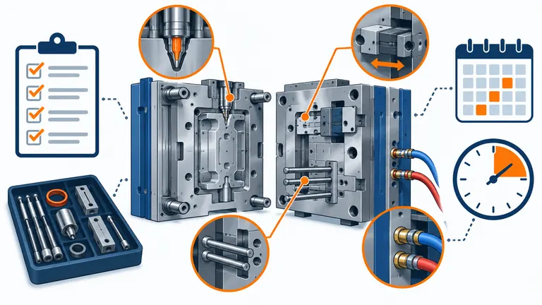
Mold maintenance is often budgeted as a percentage of tool price or handled only after a failure. Neither approach connects spending to the mechanism that wears, the production plan, or the time needed to restore an approved process. The result can be avoidable downtime or indiscriminate part replacement.
Build the budget from the mold’s actual systems, cycle exposure, resin, process, defect history, access requirements, and delivery risk. Separate routine preventive work, condition-triggered service, critical spares, planned refurbishment, and contingency downtime. The interval must follow the tool and component manufacturer’s guidance plus observed condition; there is no universal cycle count for every automotive mold.
Create a maintainable asset baseline
A reliable budget starts with knowing exactly what is being maintained. The mold record should connect asset identity, drawings, component list, material and hardness, purchased-system manuals, process limits, cavity numbering, maintenance history, and current condition.
Build a system map covering mold base guidance, cavity and core surfaces, shutoffs, slides and lifters, ejection, cooling, hydraulic or pneumatic circuits, hot runner, heaters and thermocouples, sensors, connectors, insulation, and lifting or transport equipment. For each system, record failure mode, inspection method, service access, safety controls, replaceable item, lead time, and effect on part quality or output. A valve stem and a cosmetic cavity insert have very different wear, replacement, and validation implications.
The baseline should include the approved process and current part evidence. Store the controlled mold revision, last accepted samples or boundary samples where applicable, dimensional report, cavity-specific trends, process setup record, and known concessions. Maintenance technicians need to know which surfaces and dimensions are functionally sensitive. Cleaning a vent, polishing a cavity, or adjusting a shutoff can change molding behavior or appearance; maintenance cannot be separated from product control.
Follow the equipment supplier’s instructions for proprietary systems. Husky’s hot-runner service manual, for example, distinguishes scheduled preventive procedures from service performed when required and directs users to assembly-specific torque values (Husky EMI Hot Runner Service Manual). That is a useful principle, not a maintenance schedule for every mold. The applicable mold, hot-runner, standard-component, sensor, and machine manuals govern actual work.
Photograph and record condition before production begins and after major work. Include parting-line condition, vents, gate areas, sliding contact, cooling connections, leakage evidence, corrosion, and replaced items. This makes later budgeting evidence-based rather than dependent on recollection.
Set intervals by exposure and observed condition
Calendar-only maintenance misses heavily used tools; cycle-only maintenance misses corrosion during storage, abrasive local flow, contamination, and damage during handling. Use several triggers together.
Track cycles or shots, resin and filler, molding temperature, pressure exposure, lubricant and cleaning requirements, water quality, cooling performance, stoppages, alarms, defects, and storage duration. Glass- or mineral-filled grades can increase wear in specific flow and sealing areas, while flame-retardant or corrosive environments may require different material and care decisions. Do not generalize from the resin family; review the exact grade’s processing guidance and the actual wear map.
Define inspection levels. A run-start check may verify connectors, leaks, lubrication, safety devices, and condition of visible surfaces. A planned production interval may add vent cleaning, ejector and slide review, water-flow checks, hot-runner electrical resistance or continuity checks as specified, and part-trend review. A deeper service may require controlled disassembly, measurement, replacement, reassembly, and functional testing. Only trained personnel should perform work under the applicable lockout and safety procedures.
Use condition signals to adjust the interval. Rising cavity-to-cavity variation, flash at one shutoff, unstable filling, slow slide action, cooling imbalance, water leakage, heater alarms, increasing ejection marks, or repeated unplanned stops can indicate a specific deterioration path. The action should investigate that path instead of shortening every interval equally.
Supplier recommendations can anchor proprietary components. Husky publishes preventive-maintenance kits and interval guidance for named hot-runner platforms, but those figures are product-specific and cannot be copied to an unrelated system (Husky hot-runner PM kits). Record the manufacturer, model, configuration, manual revision, and local conditions behind each interval.
After maintenance, define a release check proportionate to the work. Replacing a connector differs from welding a cavity surface. The release may include leak testing, electrical checks, dry cycling, short molding trial, first-piece inspection, cavity comparison, appearance review, or customer requalification. The budget must include that verification time.
Budget labor, parts, and lost production separately
A single maintenance allowance conceals the drivers management can act on. Build the annual plan by task and by risk.
| Budget element | Calculation basis | Evidence | Owner |
|---|---|---|---|
| Routine preventive labor | Task time × planned events | Work instructions and history | Maintenance |
| Consumables | Cleaner, lubricant, filters, seals and approved protection | BOM and usage record | Maintenance/purchasing |
| Condition inspections | Measurement or test time | Inspection plan and trend triggers | Tooling/quality |
| Critical spares | Quantity × current lead-time-adjusted cost | Failure consequence and replenishment time | Tooling/purchasing |
| Planned refurbishment | Scope by wear location and interval | Condition report and vendor quotation | Program/tooling |
| Verification after work | Trial, setup, inspection, samples | Release matrix | Quality/process |
| Planned downtime | Hours × constrained-cell impact | Production schedule | Operations/planning |
| Contingency exposure | Named failure scenarios, not a blanket percentage | Risk register | Cross-functional team |
Illustrative example—hypothetical. A mold is scheduled for six preventive services during the year. Each requires 10 technician hours, four hours of molding-cell access, and USD 350 of consumables. One planned deep service requires 32 technician hours, 12 cell hours, USD 2,500 in replacement wear items, and a dimensional check. The budget should show those quantities directly. If labor is valued at USD 60 per hour and constrained cell time at USD 180 per hour, the visible annual amounts are:
- routine labor:
6 × 10 × 60 = USD 3,600; - routine cell time:
6 × 4 × 180 = USD 4,320; - routine consumables:
6 × 350 = USD 2,100; - deep-service labor:
32 × 60 = USD 1,920; - deep-service cell time:
12 × 180 = USD 2,160; - planned wear parts: USD 2,500;
- dimensional verification: a separate quoted or internal cost.
The subtotal before dimensional verification is USD 16,600. This is not a recommended interval or company price. It demonstrates why labor, cell access, and parts must be visible. If the tool can be serviced off-line using a spare insert or another press, the downtime assumption changes. If the molding cell is not production-constrained, the internal cost interpretation may also differ.
Review actual versus plan quarterly. Record planned events completed, unplanned service, replaced parts, downtime, defects linked to tooling, and interval changes. A variance should lead to a technical explanation, not simply a larger percentage next year.
Choose spares by consequence and replenishment time
Buying one of every component wastes capital; stocking nothing turns a small failure into a long outage. Classify spares using failure likelihood, detection, production consequence, replacement time, and validation burden.
Critical ready-to-install spares may include small core pins, ejector elements, springs, seals, heaters, thermocouples, valve stems, tips, sensors, connectors, hydraulic components, or pre-fitted inserts—depending on the actual design. The list must use exact part numbers, materials, hardness, coatings, dimensions, and supplier references. A visually similar component is not necessarily interchangeable.
For each spare, state storage conditions, shelf or inspection review, preservation, quantity, location, owner, reorder trigger, and installation instructions. Elastomer seals and electronic items may have storage limits; steel components need corrosion protection. Meusburger’s guidance for O-rings, for example, addresses installation damage, cleaning compatibility, and controlled storage conditions for specific seal materials (Meusburger O-ring guidance). Apply the actual component manufacturer’s requirements.
Some spares need pre-verification. An interchangeable cavity insert should be checked for interfaces, dimensions, material, heat treatment, cooling, and actual fit. A spare heater or thermocouple needs the correct electrical characteristics and connector. If replacing the item changes a critical product surface or dimension, predefine the requalification step.
The spare decision must consider supply lead time and access. A low-cost imported standard component with a long replenishment time may deserve local stock; an expensive cavity insert may be better protected by a reviewed manufacturing data package and an approved repair plan. For overseas tools, specify locally replaceable standards where practical and confirm real availability at the destination.
Connect maintenance to production and ownership decisions
Maintenance planning is operational only when responsibility is explicit. The tool owner, operating molder, toolmaker, and purchased-system suppliers may each hold different records and obligations.
Define who performs routine work, who authorizes disassembly or steel changes, who pays for normal wear, misuse, customer design changes, and optional improvements, and who controls spare inventory. Define how the customer receives maintenance records and how urgent work is approved. These are commercial and contractual decisions as well as technical ones; obtain appropriate review rather than assuming a general practice applies.
Plan service windows against forecasts and release orders. Identify the inventory or alternate capacity needed during planned deep service. For constrained programs, align tooling work with plant shutdowns, color changes, or other scheduled downtime. If the mold is moved, include inspection before release, preservation, transport, receiving inspection, machine fit, trial, and customer approval time.
At each major service, update the asset baseline. Record parts replaced, dimensions affected, weld or rework locations, drawings revised, process changes, trial results, and next due condition. Preserve removed critical components when analysis is needed. A maintenance invoice without technical closure does not prove the mold is ready for approved production.
To request a lifecycle maintenance proposal, provide mold drawings and BOM, resin grades, forecast cycles, process conditions, current condition, defect history, critical features, customer approval rules, destination, available maintenance skills, and downtime constraints. Ask for tasks, triggers, labor, spare list, verification, exclusions, and records—not a single percentage of mold price.
Conclusion
Budget mold maintenance from actual systems and failure consequences. Separate preventive labor, cell access, consumables, spares, refurbishment, and release verification; set intervals from manufacturer guidance and condition data. Keep the asset baseline and maintenance history current so every expense protects a defined production or quality risk.