
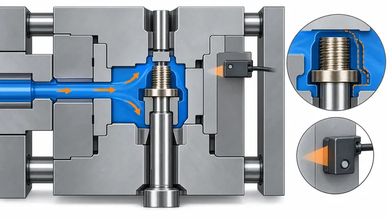
An insert can be correct when the operator loads it and still tilt during mold closing or move when the melt front applies an unbalanced force. The resulting part may hide the displacement until assembly, while a severe shift can damage shut-offs or core pins.
Control insert motion mechanically in every relevant direction, stack insert and mold tolerances, review mold-close contact and melt-force direction, verify loading and presence, and measure the finished insert from functional molded datums. Process settings can reduce force, but they should not replace positive location.
The investigation separates loading stability, close movement, filling force, process interaction and post-mold detection.
Define allowable insert location and surfaces
position, angle, protrusion, rotation and resin-free functional areas relative to molded datums must be resolved before the interface or tool is released.
Define translating assembly and electrical or sealing needs into measurable insert requirements, preserve the assumptions and verify the production-intent condition. A generic design rule or material label cannot approve the finished automotive part.
The review should begin with the physical function rather than a preferred manufacturing answer. The technical focus is position, angle, protrusion, rotation and resin-free functional areas relative to molded datums. Put that focus into the drawing, interface definition, quotation or validation plan that governs the work. Use the exact grade, geometry and condition under review, and identify connected characteristics that may move with the decision.
Use this sequence: translating assembly and electrical or sealing needs into measurable insert requirements. Assign unresolved inputs to named owners, freeze the working revision and state the next commitment that would be costly to reverse. Trials should use representative material, tooling, equipment and handling; a prototype or illustrative comparison must remain clearly identified when it is not production evidence.
The minimum inputs are insert and part CAD/drawings, datum scheme, mating hardware, exposed contacts/threads, coating or plating, movement and flash limits. Check units, conditioning, sample identity and requirement source. Request controlled customer documents instead of guessing proprietary rules. Tighter location increases nest and insert tolerance demands; functional limits should drive precision rather than a generic insert-molding target. Preserve the rejected alternative and its reason because volume, environment, appearance, assembly or equipment changes can reverse the choice.
The main failure path is specifying only nominal insert position or measuring from unstable external plastic surfaces. Isolate variables and watch coupled effects on dimensions, appearance, strength, cycle or inspection. Closure requires a controlled drawing and measurement plan define location, orientation and protected zones. Connect original evidence to part and drawing revision, cavity or fixture, material lot and process state; then record both an acceptance condition and a reaction that tells production when to stop or reopen the review.
Control variation in the incoming insert
size, form, burr, straightness, plating, orientation and batch condition that affect seating in the nest must be resolved before the interface or tool is released.
Define characterizing actual insert tolerances and creating datum contacts that reject or accommodate them safely, preserve the assumptions and verify the production-intent condition. A generic design rule or material label cannot approve the finished automotive part.
Treat this as a controlled interface between design intent and production evidence. The technical focus is size, form, burr, straightness, plating, orientation and batch condition that affect seating in the nest. Put that focus into the drawing, interface definition, quotation or validation plan that governs the work. Use the exact grade, geometry and condition under review, and identify connected characteristics that may move with the decision.
Use this sequence: characterizing actual insert tolerances and creating datum contacts that reject or accommodate them safely. Assign unresolved inputs to named owners, freeze the working revision and state the next commitment that would be costly to reverse. Trials should use representative material, tooling, equipment and handling; a prototype or illustrative comparison must remain clearly identified when it is not production evidence.
The minimum inputs are supplier drawing, capability or lot data, burr direction, springback, plating build, cleanliness, magnetism, feeder orientation and packaging. Check units, conditioning, sample identity and requirement source. Request controlled customer documents instead of guessing proprietary rules. A tight insert specification simplifies tooling but raises component cost; compliant location handles variation while potentially reducing accuracy. Preserve the rejected alternative and its reason because volume, environment, appearance, assembly or equipment changes can reverse the choice.
The main failure path is designing the mold around a perfect CAD insert or allowing burrs and oil to change seating and shut-off. Isolate variables and watch coupled effects on dimensions, appearance, strength, cycle or inspection. Closure requires incoming checks and dry-loading trials show the insert seats without damage across credible variation. Connect original evidence to part and drawing revision, cavity or fixture, material lot and process state; then record both an acceptance condition and a reaction that tells production when to stop or reopen the review.
Retain the insert through mold closing
pins, nests, magnets, spring features, vacuum or opposed support preventing drop, lift, rotation and clamp shift must be resolved before the interface or tool is released.
Define supporting the insert in all force directions and dry-cycling the mold with detection before injecting resin, preserve the assumptions and verify the production-intent condition. A generic design rule or material label cannot approve the finished automotive part.
The useful question is not whether the option can work once, but whether its boundary conditions are visible. The technical focus is pins, nests, magnets, spring features, vacuum or opposed support preventing drop, lift, rotation and clamp shift. Put that focus into the drawing, interface definition, quotation or validation plan that governs the work. Use the exact grade, geometry and condition under review, and identify connected characteristics that may move with the decision.
Use this sequence: supporting the insert in all force directions and dry-cycling the mold with detection before injecting resin. Assign unresolved inputs to named owners, freeze the working revision and state the next commitment that would be costly to reverse. Trials should use representative material, tooling, equipment and handling; a prototype or illustrative comparison must remain clearly identified when it is not production evidence.
The minimum inputs are mold orientation, insert mass, core/pin fit, support span, closing speed, robot or hand load, magnet/material behavior and clearance. Check units, conditioning, sample identity and requirement source. Request controlled customer documents instead of guessing proprietary rules. Rigid capture gives precision but raises crash risk; compliant retention protects tooling while needing verified repeatability. Preserve the rejected alternative and its reason because volume, environment, appearance, assembly or equipment changes can reverse the choice.
The main failure path is relying on gravity, trapping an insert between mismatched shut-offs or using a slender pin that bends during close. Isolate variables and watch coupled effects on dimensions, appearance, strength, cycle or inspection. Closure requires dry cycles, contact checks and sensor challenge tests demonstrate stable seating and safe mold closure. Connect original evidence to part and drawing revision, cavity or fixture, material lot and process state; then record both an acceptance condition and a reaction that tells production when to stop or reopen the review.
Balance melt flow and pressure around the insert
asymmetric flow fronts, projected area, jetting, hesitation, welds and venting that push or rotate the metal must be resolved before the interface or tool is released.
Define placing gates and flow paths to reduce unbalanced force while fully encapsulating required retention features, preserve the assumptions and verify the production-intent condition. A generic design rule or material label cannot approve the finished automotive part.
A supplier recommendation becomes actionable only when its assumptions can be checked against the released product. The technical focus is asymmetric flow fronts, projected area, jetting, hesitation, welds and venting that push or rotate the metal. Put that focus into the drawing, interface definition, quotation or validation plan that governs the work. Use the exact grade, geometry and condition under review, and identify connected characteristics that may move with the decision.
Use this sequence: placing gates and flow paths to reduce unbalanced force while fully encapsulating required retention features. Assign unresolved inputs to named owners, freeze the working revision and state the next commitment that would be costly to reverse. Trials should use representative material, tooling, equipment and handling; a prototype or illustrative comparison must remain clearly identified when it is not production evidence.
The minimum inputs are material viscosity, fill time, gate type/location, insert projection, support direction, vents, cavity pressure or simulation and machine limits. Check units, conditioning, sample identity and requirement source. Request controlled customer documents instead of guessing proprietary rules. Balanced flow reduces displacement but may move weld lines or add gates; stronger support can preserve gate freedom at higher tooling complexity. Preserve the rejected alternative and its reason because volume, environment, appearance, assembly or equipment changes can reverse the choice.
The main failure path is lowering speed until the cavity shorts, ignoring force before flow surrounds the insert or creating an air trap behind metal. Isolate variables and watch coupled effects on dimensions, appearance, strength, cycle or inspection. Closure requires simulation assumptions, short shots and pressure/location trial data show insert stability through fill. Connect original evidence to part and drawing revision, cavity or fixture, material lot and process state; then record both an acceptance condition and a reaction that tells production when to stop or reopen the review.
Establish loading and process controls
operator or robot placement, presence/orientation sensing, startup, heat, contamination and cycle changes affecting movement must be resolved before the interface or tool is released.
Define defining error-proof loading, sensor logic, stop reaction and a supported process window, preserve the assumptions and verify the production-intent condition. A generic design rule or material label cannot approve the finished automotive part.
Separate the mechanism being controlled from the document used to report it. The technical focus is operator or robot placement, presence/orientation sensing, startup, heat, contamination and cycle changes affecting movement. Put that focus into the drawing, interface definition, quotation or validation plan that governs the work. Use the exact grade, geometry and condition under review, and identify connected characteristics that may move with the decision.
Use this sequence: defining error-proof loading, sensor logic, stop reaction and a supported process window. Assign unresolved inputs to named owners, freeze the working revision and state the next commitment that would be costly to reverse. Trials should use representative material, tooling, equipment and handling; a prototype or illustrative comparison must remain clearly identified when it is not production evidence.
The minimum inputs are workholding, feeder, vision or switches, insert preheat if required, mold temperature, injection profile, cushion, startup and maintenance. Check units, conditioning, sample identity and requirement source. Request controlled customer documents instead of guessing proprietary rules. Automation reduces human variation but depends on consistent insert presentation; manual loading offers flexibility with greater verification needs. Preserve the rejected alternative and its reason because volume, environment, appearance, assembly or equipment changes can reverse the choice.
The main failure path is bypassing a nuisance sensor, changing injection profile without location checks or assuming preheat benefits every material pair. Isolate variables and watch coupled effects on dimensions, appearance, strength, cycle or inspection. Closure requires challenge tests, process-window trials and traceable alarms demonstrate missing, doubled and mis-seated inserts are contained. Connect original evidence to part and drawing revision, cavity or fixture, material lot and process state; then record both an acceptance condition and a reaction that tells production when to stop or reopen the review.
Detect movement in the finished part
location, tilt, rotation, exposed-surface flash and hidden encapsulation variation after molding must be resolved before the interface or tool is released.
Define measuring from functional plastic datums and combining dimensional checks with sections or suitable non-destructive methods, preserve the assumptions and verify the production-intent condition. A generic design rule or material label cannot approve the finished automotive part.
Close this point at the level of the specific feature, material state, process step or inspection result. The technical focus is location, tilt, rotation, exposed-surface flash and hidden encapsulation variation after molding. Put that focus into the drawing, interface definition, quotation or validation plan that governs the work. Use the exact grade, geometry and condition under review, and identify connected characteristics that may move with the decision.
Use this sequence: measuring from functional plastic datums and combining dimensional checks with sections or suitable non-destructive methods. Assign unresolved inputs to named owners, freeze the working revision and state the next commitment that would be costly to reverse. Trials should use representative material, tooling, equipment and handling; a prototype or illustrative comparison must remain clearly identified when it is not production evidence.
The minimum inputs are cavity and insert lot, gauge/CMM strategy, sample frequency, CT or section needs, vision, functional assembly and reaction plan. Check units, conditioning, sample identity and requirement source. Request controlled customer documents instead of guessing proprietary rules. Full inspection can protect high-risk features but adds cycle; validated sensing and periodic dimensional evidence may control a stable mechanism. Preserve the rejected alternative and its reason because volume, environment, appearance, assembly or equipment changes can reverse the choice.
The main failure path is checking only insert presence, averaging cavities or using a gauge that pushes the insert into acceptance. Isolate variables and watch coupled effects on dimensions, appearance, strength, cycle or inspection. Closure requires original location data, functional tests and defined containment limits confirm stable production and identify failure mode. Connect original evidence to part and drawing revision, cavity or fixture, material lot and process state; then record both an acceptance condition and a reaction that tells production when to stop or reopen the review.
Insert-movement prevention and detection checklist
Use this worksheet—the insert-movement prevention and detection checklist—during the supplier review. It is a decision aid for design the insert, mold and process so each metal insert remains correctly located through mold close and resin filling., not a substitute for the drawing, customer specification or validation record.
| Review line | Required input or evidence | Release question |
|---|---|---|
| Define allowable insert location and surfaces | insert and part CAD/drawings, datum scheme, mating hardware, exposed contacts/threads, coating or plating, movement and flash limits | Is a controlled drawing and measurement plan define location, orientation and protected zones available and traceable? |
| Control variation in the incoming insert | supplier drawing, capability or lot data, burr direction, springback, plating build, cleanliness, magnetism, feeder orientation and packaging | Is incoming checks and dry-loading trials show the insert seats without damage across credible variation available and traceable? |
| Retain the insert through mold closing | mold orientation, insert mass, core/pin fit, support span, closing speed, robot or hand load, magnet/material behavior and clearance | Is dry cycles, contact checks and sensor challenge tests demonstrate stable seating and safe mold closure available and traceable? |
| Balance melt flow and pressure around the insert | material viscosity, fill time, gate type/location, insert projection, support direction, vents, cavity pressure or simulation and machine limits | Is simulation assumptions, short shots and pressure/location trial data show insert stability through fill available and traceable? |
| Establish loading and process controls | workholding, feeder, vision or switches, insert preheat if required, mold temperature, injection profile, cushion, startup and maintenance | Is challenge tests, process-window trials and traceable alarms demonstrate missing, doubled and mis-seated inserts are contained available and traceable? |
| Detect movement in the finished part | cavity and insert lot, gauge/CMM strategy, sample frequency, CT or section needs, vision, functional assembly and reaction plan | Is original location data, functional tests and defined containment limits confirm stable production and identify failure mode available and traceable? |
For the decision to design the insert, mold and process so each metal insert remains correctly located through mold close and resin filling., read the rows together. A technically acceptable feature can still be commercially incomplete, and a complete quotation can still rely on an unverified process assumption. Mark each row accepted, accepted with a bounded action, or open. A bounded action needs an owner, due date, quantity or activity limit and the evidence required for final closure.
Worked decision scenario
Consider this decision pattern. A stamped terminal sits correctly during manual loading but leans after molding in one cavity. Dry cycling shows no movement, while short shots reveal the first flow front strikes one unsupported side. The tool adds opposed support and the gate profile is rebalanced without moving a weld into the sealing wall. Presence sensing is challenged, and terminal position is measured from molded mounting datums across startup and steady production.
For prevent insert movement injection molding, the decision remains conditional on the stated geometry, material, load, environment, quantity and acceptance method. Changing one of those inputs reopens the affected review line.
Questions to ask the supplier
- How will you demonstrate that a controlled drawing and measurement plan define location, orientation and protected zones?
- How will you demonstrate that incoming checks and dry-loading trials show the insert seats without damage across credible variation?
- How will you demonstrate that dry cycles, contact checks and sensor challenge tests demonstrate stable seating and safe mold closure?
- How will you demonstrate that simulation assumptions, short shots and pressure/location trial data show insert stability through fill?
- How will you demonstrate that challenge tests, process-window trials and traceable alarms demonstrate missing, doubled and mis-seated inserts are contained?
- How will you demonstrate that original location data, functional tests and defined containment limits confirm stable production and identify failure mode?
For prevent insert movement injection molding, a useful answer names the controlled source, identifies assumptions and exceptions, and explains how the result will be transferred into production documentation. A yes/no response without revision, sample and condition context is not sufficient for release.
Information to submit for a project-specific review
Provide insert and molded-part CAD/drawings, insert tolerances and finish, allowable location and protected surfaces, material, gate/tool concept, loading method, process records, cavity history and inspection or functional requirements. Use the AutoMoldingPro request form to keep the current files and assumptions tied to one inquiry. Detailed validation documents can follow after the initial scope is understood.
Conclusion
Prevent insert movement with positive geometry and balanced tool/process design. Verify each stage—incoming insert, loading, mold close, filling and finished location—so lower pressure is not the only defense.