
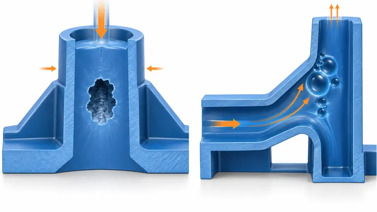
A hidden cavity inside a molded boss may be called a bubble, void or air pocket interchangeably. If the mechanism is shrinkage at the thermal center, more drying or venting may do nothing; if it is gas, more packing may hide symptoms while increasing stress.
Classify the defect using its location, shape, surface effect, section and process response. Then test a mechanism-specific hypothesis: effective packing and gate freeze for shrinkage voids; moisture, volatiles, flow trapping and venting for gas. Preserve dimensions, weight and other quality outputs while changing the process.
The investigation should move from evidence preservation to physical classification, then through packing, gas sources, design and confirmation.
Preserve samples and locate the cavity
depth, position, shape, distribution, surface bulge or sink and recurrence by cavity and time can produce a confident but wrong diagnosis or acceptance decision when its conditions are not recorded.
Define using identified non-destructive inspection where suitable, then controlled sectioning on a defined plane, isolate variables and retain original evidence. Apply customer requirements and project-specific acceptance limits instead of invented universal values.
The review should begin with the physical function rather than a preferred manufacturing answer. The technical focus is depth, position, shape, distribution, surface bulge or sink and recurrence by cavity and time. Put that focus into the drawing, interface definition, quotation or validation plan that governs the work. Use the exact grade, geometry and condition under review, and identify connected characteristics that may move with the decision.
Use this sequence: using identified non-destructive inspection where suitable, then controlled sectioning on a defined plane. Assign unresolved inputs to named owners, freeze the working revision and state the next commitment that would be costly to reverse. Trials should use representative material, tooling, equipment and handling; a prototype or illustrative comparison must remain clearly identified when it is not production evidence.
The minimum inputs are part/cavity/lot, process timestamp, part weight, images, X-ray or CT settings if used, section orientation, wall map and defect criterion. Check units, conditioning, sample identity and requirement source. Request controlled customer documents instead of guessing proprietary rules. CT can preserve 3D evidence but adds cost and interpretation; sectioning is direct and local but destructive. Preserve the rejected alternative and its reason because volume, environment, appearance, assembly or equipment changes can reverse the choice.
The main failure path is cutting random samples without location reference or destroying all evidence before comparing process history. Isolate variables and watch coupled effects on dimensions, appearance, strength, cycle or inspection. Closure requires correlated external, imaging and section records show where the cavity sits relative to thick sections and flow features. Connect original evidence to part and drawing revision, cavity or fixture, material lot and process state; then record both an acceptance condition and a reaction that tells production when to stop or reopen the review.
Test the shrinkage-void hypothesis
a cavity near the thermal center where frozen skin prevents inward surface collapse and feed pressure is insufficient can produce a confident but wrong diagnosis or acceptance decision when its conditions are not recorded.
Define checking effective pack transmission, gate freeze and volumetric contraction before simply increasing settings, isolate variables and retain original evidence. Apply customer requirements and project-specific acceptance limits instead of invented universal values.
Treat this as a controlled interface between design intent and production evidence. The technical focus is a cavity near the thermal center where frozen skin prevents inward surface collapse and feed pressure is insufficient. Put that focus into the drawing, interface definition, quotation or validation plan that governs the work. Use the exact grade, geometry and condition under review, and identify connected characteristics that may move with the decision.
Use this sequence: checking effective pack transmission, gate freeze and volumetric contraction before simply increasing settings. Assign unresolved inputs to named owners, freeze the working revision and state the next commitment that would be costly to reverse. Trials should use representative material, tooling, equipment and handling; a prototype or illustrative comparison must remain clearly identified when it is not production evidence.
The minimum inputs are wall and boss thickness, gate/runner size, transfer point, pressure at cavity if available, hold pressure/time, check-ring behavior, mold temperature and weight plateau. Check units, conditioning, sample identity and requirement source. Request controlled customer documents instead of guessing proprietary rules. More pack can reduce shrinkage voids but increase flash, stress and dimensions; geometry or gate change may be the robust route. Preserve the rejected alternative and its reason because volume, environment, appearance, assembly or equipment changes can reverse the choice.
The main failure path is raising pack beyond safe tool or part limits, mistaking a surface sink for a gas bubble or ignoring a frozen gate. Isolate variables and watch coupled effects on dimensions, appearance, strength, cycle or inspection. Closure requires weight/pressure studies, sections and dimensional/sink checks demonstrate whether effective packing changes the cavity. Connect original evidence to part and drawing revision, cavity or fixture, material lot and process state; then record both an acceptance condition and a reaction that tells production when to stop or reopen the review.
Test moisture, volatile and trapped-gas causes
water vapor, decomposition, air entrainment or flow-front convergence forming physical gas pockets can produce a confident but wrong diagnosis or acceptance decision when its conditions are not recorded.
Define checking grade-specific drying and material history, then flow and vent evidence in controlled trials, isolate variables and retain original evidence. Apply customer requirements and project-specific acceptance limits instead of invented universal values.
The useful question is not whether the option can work once, but whether its boundary conditions are visible. The technical focus is water vapor, decomposition, air entrainment or flow-front convergence forming physical gas pockets. Put that focus into the drawing, interface definition, quotation or validation plan that governs the work. Use the exact grade, geometry and condition under review, and identify connected characteristics that may move with the decision.
Use this sequence: checking grade-specific drying and material history, then flow and vent evidence in controlled trials. Assign unresolved inputs to named owners, freeze the working revision and state the next commitment that would be costly to reverse. Trials should use representative material, tooling, equipment and handling; a prototype or illustrative comparison must remain clearly identified when it is not production evidence.
The minimum inputs are resin grade, moisture method/result, dryer dew point/time/airflow, storage, regrind, melt history, injection profile, weld location and vents. Check units, conditioning, sample identity and requirement source. Request controlled customer documents instead of guessing proprietary rules. Drying protects hygroscopic resin but excessive time/heat can degrade some grades; follow current supplier guidance for the exact material. Preserve the rejected alternative and its reason because volume, environment, appearance, assembly or equipment changes can reverse the choice.
The main failure path is assuming dryer temperature proves dryness or changing drying and fill speed together so the cause stays ambiguous. Isolate variables and watch coupled effects on dimensions, appearance, strength, cycle or inspection. Closure requires moisture records, short shots, vent checks and repeat sections show whether gas generation or entrapment follows the defect. Connect original evidence to part and drawing revision, cavity or fixture, material lot and process state; then record both an acceptance condition and a reaction that tells production when to stop or reopen the review.
Review geometry, gates and thermal balance
thick transitions, isolated mass, flow splits, ribs/bosses and cooling differences that create either mechanism can produce a confident but wrong diagnosis or acceptance decision when its conditions are not recorded.
Define mapping thermal centers and air traps with the actual gate and cooling concept, supported by simulation where appropriate, isolate variables and retain original evidence. Apply customer requirements and project-specific acceptance limits instead of invented universal values.
A supplier recommendation becomes actionable only when its assumptions can be checked against the released product. The technical focus is thick transitions, isolated mass, flow splits, ribs/bosses and cooling differences that create either mechanism. Put that focus into the drawing, interface definition, quotation or validation plan that governs the work. Use the exact grade, geometry and condition under review, and identify connected characteristics that may move with the decision.
Use this sequence: mapping thermal centers and air traps with the actual gate and cooling concept, supported by simulation where appropriate. Assign unresolved inputs to named owners, freeze the working revision and state the next commitment that would be costly to reverse. Trials should use representative material, tooling, equipment and handling; a prototype or illustrative comparison must remain clearly identified when it is not production evidence.
The minimum inputs are CAD wall map, gate/runner, fill sequence, vent locations, cooling layout, material data and process-window records. Check units, conditioning, sample identity and requirement source. Request controlled customer documents instead of guessing proprietary rules. Coring thick sections reduces void risk and cycle but changes stiffness; gate changes improve feeding or venting while moving welds and vestiges. Preserve the rejected alternative and its reason because volume, environment, appearance, assembly or equipment changes can reverse the choice.
The main failure path is tuning settings around a fundamentally unfeedable mass or adding a vent where the pocket is actually a shrinkage void. Isolate variables and watch coupled effects on dimensions, appearance, strength, cycle or inspection. Closure requires tool/flow review and molded short-shot/section data connect geometry to the confirmed mechanism. Connect original evidence to part and drawing revision, cavity or fixture, material lot and process state; then record both an acceptance condition and a reaction that tells production when to stop or reopen the review.
Protect coupled quality characteristics
dimensions, sink, residual stress, weld strength, appearance and cycle that can move while the cavity improves can produce a confident but wrong diagnosis or acceptance decision when its conditions are not recorded.
Define monitoring affected and neighboring outputs during every diagnostic change, isolate variables and retain original evidence. Apply customer requirements and project-specific acceptance limits instead of invented universal values.
Separate the mechanism being controlled from the document used to report it. The technical focus is dimensions, sink, residual stress, weld strength, appearance and cycle that can move while the cavity improves. Put that focus into the drawing, interface definition, quotation or validation plan that governs the work. Use the exact grade, geometry and condition under review, and identify connected characteristics that may move with the decision.
Use this sequence: monitoring affected and neighboring outputs during every diagnostic change. Assign unresolved inputs to named owners, freeze the working revision and state the next commitment that would be costly to reverse. Trials should use representative material, tooling, equipment and handling; a prototype or illustrative comparison must remain clearly identified when it is not production evidence.
The minimum inputs are critical dimensions, part weight, surface criteria, mechanical/pressure function, cycle, process alarms and sample identity. Check units, conditioning, sample identity and requirement source. Request controlled customer documents instead of guessing proprietary rules. A focused experiment improves diagnosis; production release still needs evidence across the approved process and part requirements. Preserve the rejected alternative and its reason because volume, environment, appearance, assembly or equipment changes can reverse the choice.
The main failure path is accepting a cavity reduction that creates flash, oversize features or weak flow reunions elsewhere. Isolate variables and watch coupled effects on dimensions, appearance, strength, cycle or inspection. Closure requires a multi-output trial record shows the correction improves the defect without moving another requirement out of control. Connect original evidence to part and drawing revision, cavity or fixture, material lot and process state; then record both an acceptance condition and a reaction that tells production when to stop or reopen the review.
Confirm the mechanism and production reaction
sustained absence or bounded acceptance of internal cavities under representative lots, cavities and process conditions can produce a confident but wrong diagnosis or acceptance decision when its conditions are not recorded.
Define running confirmation, defining detection frequency and linking reaction limits to the known failure path, isolate variables and retain original evidence. Apply customer requirements and project-specific acceptance limits instead of invented universal values.
Close this point at the level of the specific feature, material state, process step or inspection result. The technical focus is sustained absence or bounded acceptance of internal cavities under representative lots, cavities and process conditions. Put that focus into the drawing, interface definition, quotation or validation plan that governs the work. Use the exact grade, geometry and condition under review, and identify connected characteristics that may move with the decision.
Use this sequence: running confirmation, defining detection frequency and linking reaction limits to the known failure path. Assign unresolved inputs to named owners, freeze the working revision and state the next commitment that would be costly to reverse. Trials should use representative material, tooling, equipment and handling; a prototype or illustrative comparison must remain clearly identified when it is not production evidence.
The minimum inputs are sample size by risk, cavities, lots, startup and steady state, inspection sensitivity, acceptance authority, containment and change triggers. Check units, conditioning, sample identity and requirement source. Request controlled customer documents instead of guessing proprietary rules. Frequent destructive inspection gives visibility but consumes parts; validated weight or process proxies may reduce burden only after correlation. Preserve the rejected alternative and its reason because volume, environment, appearance, assembly or equipment changes can reverse the choice.
The main failure path is closing from one passing section or using a sampling method unable to detect the specified cavity. Isolate variables and watch coupled effects on dimensions, appearance, strength, cycle or inspection. Closure requires traceable confirmation and control-plan reaction demonstrate that production can recognize and contain recurrence. Connect original evidence to part and drawing revision, cavity or fixture, material lot and process state; then record both an acceptance condition and a reaction that tells production when to stop or reopen the review.
Void-versus-gas diagnostic matrix
Use this worksheet—the void-versus-gas diagnostic matrix—during the supplier review. It is a decision aid for classify an internal cavity mechanism before changing packing, drying, venting, geometry or material., not a substitute for the drawing, customer specification or validation record.
| Review line | Required input or evidence | Release question |
|---|---|---|
| Preserve samples and locate the cavity | part/cavity/lot, process timestamp, part weight, images, X-ray or CT settings if used, section orientation, wall map and defect criterion | Is correlated external, imaging and section records show where the cavity sits relative to thick sections and flow features available and traceable? |
| Test the shrinkage-void hypothesis | wall and boss thickness, gate/runner size, transfer point, pressure at cavity if available, hold pressure/time, check-ring behavior, mold temperature and weight plateau | Is weight/pressure studies, sections and dimensional/sink checks demonstrate whether effective packing changes the cavity available and traceable? |
| Test moisture, volatile and trapped-gas causes | resin grade, moisture method/result, dryer dew point/time/airflow, storage, regrind, melt history, injection profile, weld location and vents | Is moisture records, short shots, vent checks and repeat sections show whether gas generation or entrapment follows the defect available and traceable? |
| Review geometry, gates and thermal balance | CAD wall map, gate/runner, fill sequence, vent locations, cooling layout, material data and process-window records | Is tool/flow review and molded short-shot/section data connect geometry to the confirmed mechanism available and traceable? |
| Protect coupled quality characteristics | critical dimensions, part weight, surface criteria, mechanical/pressure function, cycle, process alarms and sample identity | Is a multi-output trial record shows the correction improves the defect without moving another requirement out of control available and traceable? |
| Confirm the mechanism and production reaction | sample size by risk, cavities, lots, startup and steady state, inspection sensitivity, acceptance authority, containment and change triggers | Is traceable confirmation and control-plan reaction demonstrate that production can recognize and contain recurrence available and traceable? |
For the decision to classify an internal cavity mechanism before changing packing, drying, venting, geometry or material., read the rows together. A technically acceptable feature can still be commercially incomplete, and a complete quotation can still rely on an unverified process assumption. Mark each row accepted, accepted with a bounded action, or open. A bounded action needs an owner, due date, quantity or activity limit and the evidence required for final closure.
Worked decision scenario
Consider this decision pattern. A thick mounting boss shows an internal cavity on CT. It lies at the thermal center and appears as one irregular pocket, while moisture records are within the resin supplier’s range. A hold-time/weight study shows the gate freezes early and extra machine pressure no longer increases weight. The team cores the boss and enlarges the feed path, then checks dimensions, sink and pull load. The correction is confirmed across cavities rather than recorded as “better drying.”
For voids vs gas bubbles injection molding, the decision remains conditional on the stated geometry, material, load, environment, quantity and acceptance method. Changing one of those inputs reopens the affected review line.
Questions to ask the supplier
- How will you demonstrate that correlated external, imaging and section records show where the cavity sits relative to thick sections and flow features?
- How will you demonstrate that weight/pressure studies, sections and dimensional/sink checks demonstrate whether effective packing changes the cavity?
- How will you demonstrate that moisture records, short shots, vent checks and repeat sections show whether gas generation or entrapment follows the defect?
- How will you demonstrate that tool/flow review and molded short-shot/section data connect geometry to the confirmed mechanism?
- How will you demonstrate that a multi-output trial record shows the correction improves the defect without moving another requirement out of control?
- How will you demonstrate that traceable confirmation and control-plan reaction demonstrate that production can recognize and contain recurrence?
For voids vs gas bubbles injection molding, a useful answer names the controlled source, identifies assumptions and exceptions, and explains how the result will be transferred into production documentation. A yes/no response without revision, sample and condition context is not sufficient for release.
Information to submit for a project-specific review
Provide part CAD and wall sections, defect images/CT/sections, cavity and lot history, exact resin and drying data, gate/runner/cooling layout, process and weight records, functional risk and customer acceptance method. Use the AutoMoldingPro request form to keep the current files and assumptions tied to one inquiry. Detailed validation documents can follow after the initial scope is understood.
Conclusion
Do not use “bubble” as a root cause. Locate and section the cavity, test packing versus gas mechanisms separately, and release only a correction that also protects dimensions, stress, appearance and function.