
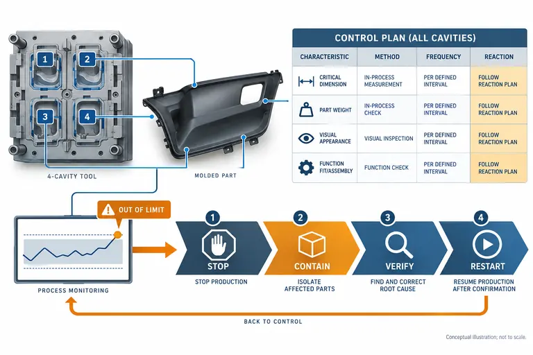
A control plan can list many checks and still fail to control production. Vague characteristics, frequencies such as “periodic,” and reaction columns that say only “inform supervisor” do not tell operators what to measure, what to stop, or which product to contain.
Build the control plan from process flow, risk analysis, drawing and customer requirements. For every controlled characteristic, define the product or process feature, method, sample and frequency, record, specification, reaction, containment boundary, authority, and restart evidence. Keep it synchronized with the actual mold, machine, material, gauges, and production phase.
Link each control to a requirement and failure mechanism
Begin with the released drawing, specifications, special-characteristic designations, process flow, PFMEA, lessons learned, customer-specific requirements, and demonstrated process data. Trace every row to why the control exists. If a dimension affects connector fit, name that function; if drying protects a hydrolysis-sensitive resin, link the material requirement and defect risk.
Do not copy every drawing dimension into one document without prioritization. The control plan is a manufacturing control strategy, while complete layout inspection may be managed elsewhere. Include product characteristics that require ongoing prevention or detection and process parameters that maintain the approved state. Customer-designated special characteristics require the customer’s prescribed symbols and controls.
For multi-cavity molds, decide whether results are recorded by cavity. Pooling samples may hide a cavity-specific drift. Include mold configuration, active cavities, interchangeable inserts, and first-off checks after maintenance. For insert molding, control insert identity, orientation, presence, and position in addition to final dimensions.
AIAG’s Control Plan 1st Edition provides current guidance on developing and using control plans, links to APQP, and safe-launch considerations (AIAG Control Plan). Use the licensed manual and applicable customer requirements for mandated format and details; a blog checklist is not a substitute.
Map controls across receiving, material preparation, setup, startup, steady production, inspection, rework if permitted, packaging, and shipment. A strong final check cannot compensate for unverified material or an uncontrolled startup.
Specify characteristic, method, and evidence so another shift can execute it
Each row should be unambiguous enough for a trained person to perform without asking the author what was intended.
| Field | Useful definition | Weak wording to avoid |
|---|---|---|
| Characteristic | Feature ID, cavity relevance and requirement source | “Critical dimensions” |
| Specification | Numerical or categorical acceptance with revision | “Per drawing” when several revisions circulate |
| Method | Gauge/test ID, fixture, condition and work instruction | “Check visually” |
| Sample/frequency | Quantity, cavities, time/lot/startup trigger | “Random” or “periodic” |
| Record | System/form and data retained | Check mark with no traceability |
| Reaction | Stop, contain, verify, escalate and restart steps | “Adjust if needed” |
Measurement conditions matter for plastics. Define time after molding, temperature, moisture conditioning, fixture state, and datum simulation where these can affect results. Confirm the measurement system is suitable for tolerance and use. A high-resolution display does not prove measurement capability.
For process parameters, distinguish setup targets, validated windows, alarms, and monitored signals. Machine setpoints, actual values, and cavity response are not interchangeable. State whether a deviation requires immediate stop or engineering review. Password-protect recipes and record revisions where feasible.
Visual checks need boundary samples, lighting, viewing distance, zones, and defect definitions when appearance matters. Attribute gauges need calibration or controlled verification and version identity. Functional gauges should represent assembly without masking excessive force.
Records must link to part, revision, batch, cavity, material lot, mold, process revision, inspector, date/time, result, and disposition as appropriate. This allows trends and containment, not just audit presentation.
Choose frequencies from risk and process behavior, then define triggers
No universal “one per shift” rule fits every molded characteristic. Frequency should reflect failure severity, occurrence mechanism, detection opportunity, process stability, cycle and cavity count, automated monitoring, customer requirement, and containment risk.
Use event-based checks at setup, material change, mold change, maintenance, cavity activation, recipe change, restart after interruption, and first production after approval. Use time-, quantity-, or lot-based sampling during steady production. Continuous monitoring can control some process variables, but sensors need limits, calibration, data integrity, and reaction rules.
Establish frequencies conservatively during launch or safe launch, then adjust only through controlled evidence and customer authorization where required. A stable capability study can support a change, but it does not remove controls for assignable events such as wrong resin or damaged tooling.
Illustrative example—hypothetical, not an AutoMoldingPro project. A four-cavity housing has one connector datum, one appearance zone, and a material-drying requirement. Startup checks cover all cavities; steady production rotates cavity samples at a defined quantity; the dryer dew point and temperature are monitored continuously with alarms; a full check is triggered after a stoppage exceeding the approved limit. The example illustrates different control mechanisms, not universal frequencies.
Review actual data periodically. If failures occur between samples, increase prevention, monitoring, or sampling and investigate the mechanism. If a control never detects relevant variation, confirm whether the process is genuinely stable or the method is insensitive. Frequency optimization should improve risk control, not simply reduce inspection labor.
Write reaction plans that protect product and restore a known state
A reaction begins with the signal: out-of-spec result, trend rule, alarm, missing material record, wrong insert, broken cavity feature, or failed gauge verification. It must tell production what happens immediately.
Define stop or hold authority; isolate material since the last known conforming check; identify affected machines, cavities, lots, containers, and shipments; notify named roles; verify the measurement; investigate cause; correct the process under authorization; inspect or disposition contained product; and document restart evidence. If customer notification or deviation is required, identify who decides and communicates.
Do not permit operators to adjust around a dimensional failure without limits. Uncontrolled parameter changes can conceal tool, material, cooling, or measurement problems and invalidate the approved process. Define allowed adjustments, escalation thresholds, and who can revise the recipe.
Restart criteria might include corrected equipment, verified material, successful first-off from every active cavity, acceptable functional test, restored process signature, gauge verification, and quality release. Link temporary actions to an expiry and permanent corrective action.
Test reaction plans with scenarios. Ask a shift to respond to a failed cavity-3 dimension, a dryer alarm, an unreadable material lot, and a broken insert sensor. Check whether records identify the containment boundary. Correct ambiguous instructions before production pressure exposes them.
Maintain the control plan as a living production baseline
Review the plan when the drawing, material, supplier, mold, cavity configuration, machine, process, gauge, packaging, location, software, or customer requirement changes. Also review after complaints, scrap trends, maintenance discoveries, audit findings, and corrective actions.
Control document revision and effective date. Remove obsolete copies from the floor, train affected personnel, update work instructions and inspection programs, and preserve approval. Confirm the PFMEA and process flow remain aligned; inconsistent documents create conflicting reaction rules.
At an RFQ or supplier review, request the proposed control-plan architecture: characteristics, cavity strategy, methods, frequencies, records, traceability, reaction and launch controls. Provide drawing and special characteristics, volumes, customer format, submission level, material condition, appearance standards, testing, and retention requirements.
For a production feasibility discussion, contact AutoMoldingPro with the released part data, annual demand, material, critical functions, validation scope, and customer-specific requirements. The output should identify proposed controls and evidence gaps, while final approval stays with the authorized customer and program team.
Audit the plan against an actual order from material receipt to shipment. Observe whether the operator can find the current recipe, distinguish every active cavity, access the specified gauge, recognize a boundary sample, enter actual data, and execute the reaction without informal help. Compare labels and records with physical stock. Then trace one failure through hold, investigation, disposition, corrective action, and restart. This floor exercise often exposes missing permissions, obsolete work instructions, unrealistic frequencies, or containment boundaries that a desk review cannot see.
Control plans also need a clear relationship to automated inspection. A camera or sensor does not close a row merely because it reports a result. Define the inspected feature, algorithm or program revision, challenge pieces, confidence threshold, reject mechanism, bypass control, data retention, and reaction to equipment fault. Verify false accept and false reject risk using representative defects. If an automated system is unavailable, the approved contingency must provide equivalent protection or stop production; an undocumented manual workaround is not a control.
Conclusion
A usable control plan connects each characteristic to a risk, defines an executable method and frequency, and gives a containment-and-restart reaction. Build it from controlled requirements, prove it on the floor, review its data, and revise it whenever the approved production state changes.