
Stage-Specific Service
Automotive Insert Molding, Overmolding & Assembly
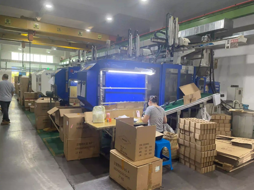
Develop a controlled process where resin, metal inserts, terminals, substrates, elastomers, and downstream assembly must work together. Component condition and loading control are part of the molding problem.
When This Route Fits
Use this route for threaded inserts, terminals, busbars, seals, soft-touch features, multi-component subassemblies, or molded parts that need controlled secondary operations. Functional requirements must be defined beyond appearance alone.
Component, Material, and Functional Inputs
Unknown items can remain open, but the quote and next gate must identify them.
1
3D and 2D data for every insert, substrate and finished assembly
2
Material grades, plating, cleanliness and surface-treatment specifications
3
Retention, pull-out, leak, electrical or torque requirements
4
Insert supply responsibility, packaging and incoming inspection criteria
5
Expected volume, automation target and validation method
Insert, Overmold, and Assembly Development
Each step produces a decision or record needed by the next stage.
1. Qualify incoming components
Confirm drawings, materials, plating, cleanliness, orientation, dimensions, packaging, ownership, and incoming inspection for inserts or substrates.
2. Approve loading and protection
Define nests, datums, anti-rotation, detection, shutoffs, pin protection, access, mistake proofing, and safe recovery from a misload.
3. Develop the molding interface
Review preheat, pressure, flow, venting, flash, deformation, bond/mechanical lock, weld lines, residual stress, cooling, and ejection.
4. Trial functional evidence
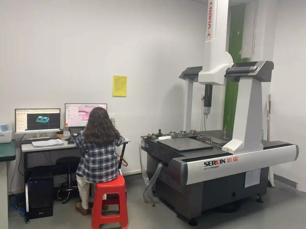
Measure insert position and flash, then perform contracted retention, torque, leak, seal, electrical, bond, or assembly checks.
5. Define secondary operations
Approve work sequence, fixtures, joining controls, component traceability, visual standards, inspection points, and packaging.
6. Release work instructions
Lock approved components, loading method, process window, reaction plan, inspection, sample retention, and authorized changes.
Contracted Deliverables
The quotation identifies which items, samples, records, and revision loops are included.
1
Process-focused DFM and interface review
2
Mold and loading concept
3
Insert or substrate incoming-control plan
4
Trial samples and agreed dimensional or functional checks
5
Assembly work instruction and packaging plan when included
Acceptance and Release Criteria
- Insert/substrate specifications, supply condition, incoming limits, and orientation are controlled.
- Loading detection and mold protection address missing, doubled, reversed, or out-of-position components.
- Position, flash, appearance, and contracted functional tests meet defined methods and criteria.
- Assembly sequence, work instructions, traceability, and packaging are approved for repeat orders.
Customer-specific standards, submission levels, test methods, sample quantities, and approval authority must be named in the RFQ or purchase requirement.
Risks That Change the Scope
These issues should trigger clarification, test planning, or written disposition—not silent assumptions.
Insert movement or damage
Injection pressure, weak location, terminal packaging, or loading variation can shift or deform the component.
Flash at critical interfaces
Shutoff wear and component variation can create flash at seals, threads, contacts, or assembly datums.
Bond assumptions
A resin/elastomer or resin/metal combination requires surface, process, geometry, and test evidence.
Mixed component status
Wrong plating, revision, orientation, or incoming lot can pass visual molding checks but fail later function.
Commercial Drivers and Boundaries
Pricing depends on insert cost and tolerance, loading method, cavities, bond risk, fixtures, automation, test cycle, assembly content, scrap exposure and supply-chain responsibility.
Chemical bonding, sealing or electrical performance is not guaranteed from generic material compatibility tables. Validation with production-intent materials and defined test conditions is required.
Assess an Insert or Assembly Program
Send the current stage and available baseline first. The response will identify missing inputs, the next approval gate, and the scope that can be responsibly quoted.