
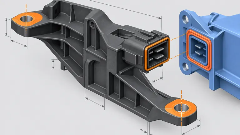
Conceptual illustration; not to scale.
When every dimension on a plastic-part drawing is tightened, the drawing may look precise while the product definition becomes harder to manufacture and inspect. Tooling corrections increase, measurement systems become slower, and suppliers may quote risk allowances instead of a clear production plan. The team can spend more money without improving the assembly that the tolerance was meant to protect.
The tolerances that need to be tight are the ones that protect a defined function, interface, safety-related characteristic or validated appearance requirement. Identify the failure mode first, allocate the available variation to the features that influence it, then choose a verification method that can resolve the requirement. Use broader, documented limits for features whose variation does not affect the part’s function. A tight number without a functional reason is a cost request, not an engineering decision.
This is a tolerance-allocation guide, not a complete tolerance-chain tutorial. For the broader input package used in an automotive RFQ, see the published automotive injection molding RFQ checklist.
Translate the product function into a feature decision
Why this matters: A nominal dimension is not automatically important because it is small, visible or close to another surface. The first task is to connect each candidate feature to a real product outcome: assembly, retention, motion, electrical alignment, load transfer, clearance, sealing interface or appearance. Without that connection, a tolerance review becomes a debate over preferred numbers.
Write the failure statement in plain language. “Connector cannot be inserted,” “clip releases below the required assembly condition,” “housing interferes with the bracket,” and “visible gap exceeds the appearance limit” are useful statements. “Dimension must be accurate” is not. Identify whether the risk is a size, location, orientation, profile, form, surface condition or material-state issue. The same nominal size can require different controls depending on how the part is used.
Next, map the feature to its mating geometry and direction of sensitivity. A hole diameter may need enough clearance for a fastener but have little effect on location; the hole position may be the real driver. A boss height may control clamp load only after the mating screw, washer and bracket stack are considered. A decorative edge may need a controlled profile in the viewing zone but not the same limit on an unseen flange.
Separate design requirements from process preferences. A customer may require a special characteristic or a specific inspection report; that requirement is not replaced by a supplier’s normal molding tolerance. Conversely, a supplier may propose a process control or a fixture that is useful but not necessary to place on the drawing. Keep the product definition, control plan and inspection plan linked without putting every process detail into the part drawing.
Review the feature list with design, manufacturing, quality and purchasing together. Purchasing needs a comparable scope; engineering needs function; quality needs an objective acceptance rule; manufacturing needs a feasible process and measurement method. The decision is stronger when all four can explain what failure the tolerance prevents.
A useful review also records how much uncertainty the assembly already has. A plastic feature may not need a narrow tolerance if the mating metal bracket has generous clearance, while a nominally large feature may need a location control because several parts accumulate in one direction. Write the relationship in the characteristic list so a future supplier sees the reason instead of only the number. Revisit the classification when the mating part, material or assembly sequence changes.
Distinguish size, location, orientation and free-state behavior
Why this matters: Over-tightening often happens because teams use a linear plus/minus dimension to solve a geometric problem. A part can have every length within limits and still have a hole pattern tilted, a mounting face warped or a connector shifted relative to the assembly datum.
Use the control type that matches the failure. Size controls the feature’s material boundary or fit. Position controls the location of a feature of size relative to datums. Profile can control a complex surface or boundary. Orientation controls angular relationship. Flatness or form may be relevant when a surface must seat without a datum reference. The governing drafting system, such as ASME Y14.5 or an applicable ISO GPS standard, determines the interpretation and should be named on the product definition.
Then decide whether the part is evaluated in a free state or a constrained state. A thin cover may be flexible enough to pass a free-state profile but fail when it is screwed to the vehicle bracket. A clamp can also hide a warpage problem by forcing a part into a position that the assembly will not reproduce. The inspection method should recreate the functional constraint when the requirement concerns assembled behavior, and it should preserve a free-state check when deformation itself is a risk.
Material state is another dimension-like variable. Moisture, temperature, reinforcement orientation and post-mold relaxation can move a plastic feature without a mold change. If a tolerance depends on a conditioned nylon state, the condition belongs in the acceptance definition. Do not solve an undocumented material-state problem by tightening the drawing.
Finally, confirm the measurement capability. A CMM, vision system, functional gage and hand gage answer different questions. A high-resolution instrument cannot remove fixture distortion, poor datum simulation or uncertainty. ISO 14253-1 specifically addresses conformity decisions close to limits with measurement uncertainty in view. If a feature is so tight that the method cannot separate conforming from nonconforming parts, either improve the method, change the control, or revisit the requirement.
This distinction also improves corrective action. A size failure points toward a diameter, wall or core correction; a location failure may point toward datum selection, shrinkage direction, insert position or process balance. An orientation failure may require cooling, support or a geometric control rather than a local dimensional change. The inspection report should identify the control type and setup that generated the result, so the toolmaker does not select a correction from a misleading linear measurement.
Use a function-first decision matrix
Why this matters: A decision matrix makes the tradeoff visible before the mold is designed. It should record the feature’s importance, the reason for control, the required evidence and the expected cost effect. “Cost” includes steel complexity, process window, inspection time, gage investment, sorting and the risk of repeated tool corrections.
Use the matrix to rank each feature by consequence, choose the control that expresses the function, assign evidence that can resolve it, and price the added tool and inspection work only where the risk justifies it.
| Feature importance | Tolerance question | Verification method | Manufacturing and inspection cost effect | Decision guidance |
|---|---|---|---|---|
| Safety or regulated interface | What failure could create a safety or legal concern? | Customer-specified test plus validated dimensional method | May require dedicated controls, traceability and escalation | Use the approved requirement; do not relax without design authority |
| Primary assembly locator | Does this feature establish the part’s position in the vehicle or subassembly? | Datum-based CMM, functional fixture or both | Higher fixture and correction sensitivity | Protect the datum relationship, not every adjacent surface |
| Retention or moving interface | Does size, position or form control engagement, travel or release? | Functional assembly test plus targeted dimensions | May require cycle/force testing and special gage | Tighten only the dimensions linked to the failure mode |
| Internal component seat | Does the feature control sensor, insert or connector fit? | CMM/profile and authorized mating component | Moderate to high; access can drive inspection method | Define the seating direction, support condition and material state |
| Cosmetic viewing zone | Is there an approved appearance limit or master sample? | Controlled visual inspection, profile or surface method | Lighting, samples and operator training add cost | Use appearance criteria; do not substitute blanket dimensional tightness |
| Structural but non-locating wall | Does thickness affect strength, heat, flow or durability? | Targeted thickness or process control | May require destructive checks or process monitoring | Link the limit to load, thermal or molding evidence |
| Clearance or keep-out | Could variation create contact, rub or assembly blockage? | Fixture, scan or mating-part check | Cost depends on accessibility and quantity | Control the boundary in the direction of possible contact |
| General envelope | Does the outer form affect packaging or adjacent clearance? | Sampled CMM/vision check | Usually lower if not functionally sensitive | Use a reasonable general requirement and confirm fit |
To use the matrix, start with the consequence column and work left to right. If the consequence is not defined, stop and ask the product owner for the function. If a functional test is the only meaningful proof, do not assume a tighter dimensional limit automatically improves it. If a dimension is required for a customer-specific PPAP characteristic, record that requirement separately from the internal cost preference.
After the first pass, review the high-cost rows with the supplier. Ask which feature drives mold complexity, which one drives measurement time and which one drives assembly validation. A feature can be important without requiring a narrow numerical tolerance if a functional gage is the better control. Conversely, a broad-looking profile can be critical when it defines a clearance boundary. Record a reason for every tight requirement and a reason for every deliberate general requirement. If no one can state the failure prevented, leave the item at the normal drawing rule until the design authority resolves it. The matrix should be revisited after DFM, because gate location, fiber orientation, cooling and ejection can change which features are practical to control.
Illustrative example: a clip pocket is difficult to inspect directly, but the assembled clip either seats or does not. The dimensional location remains controlled for diagnosis, while a fit gage becomes the release evidence. A nearby cosmetic rib is measured during development but is not elevated to the same production control because it does not change the clip function.
Communicate a tight requirement as a controlled package
Why this matters: Suppliers struggle when a drawing calls out a tight dimension but the RFQ does not identify the material, measurement state, sample quantity, datum fixture or approval evidence. The supplier may either add a conservative price or return a generic feasibility statement. Neither outcome helps the buyer compare capable proposals.
For each tight characteristic, include the drawing reference, function, tolerance type, datum frame, material grade, state at measurement, fixture concept, instrument or method, sample timing and reaction plan. Add the mating part or interface control information needed to judge the function. If a customer requires a particular capability statistic, sampling rule or report format, identify it as a customer requirement rather than an assumed universal rule.
Ask the supplier to return four items: a feasibility comment, the proposed process control, the inspection evidence and the cost or lead-time impact of the requirement. Require the response to list exclusions. For example, a CMM report may be included while a functional gage, external test or 100% sort is conditional. This prevents a later argument that “inspection included” meant every validation activity.
For a mold, ask where the feature is created: cavity, core, insert, slide, shutoff or post-process operation. Ask which steel component would be corrected if the feature is out and whether the proposed design supports a controlled correction. A location issue caused by shrinkage or fiber orientation may not be solved by removing steel from one surface. This is where tolerance allocation connects to tooling strategy, without turning the part drawing into a mold-design document.
Use the same matrix when comparing quotes. A supplier who proposes a different gage may still be equivalent if the method reproduces the functional datum and resolves the requirement. A lower price that omits the critical check is not a comparable offer. The automotive quote comparison guide can be used after the technical scope is normalized.
Ask the supplier to call out any requirement that would need a special insert, dedicated fixture, additional cavity sampling or controlled environmental measurement. The response should separate a one-time launch activity from a recurring lot-control activity. That distinction helps purchasing compare quotations and helps the program team understand what will remain after production release. It also gives design a chance to remove a needless burden before the tool is built.
Apply the matrix to an illustrative housing example
Why this matters: Illustrative example: a molded electronics housing has a connector opening, two mounting slots, an internal board support and a broad outside wall. The first drawing applies a tight linear tolerance to the overall length, every boss diameter and all rib locations. The team cannot explain which failures those limits prevent, and the supplier predicts long CMM inspection time.
The review starts with the assembly. The mounting plane and slot axes establish the vehicle bracket relationship. Connector position is checked relative to that frame and with an authorized connector gauge. The board support height is linked to the board seating and screw stack. The general wall and non-contact ribs receive process-appropriate controls, while the outside length is kept only as tight as the adjacent clearance requires. The rib locations remain documented for DFM, but they are not automatically elevated to special characteristics.
The cost effect is then discussed honestly. A dedicated fixture may cost more than a loose CMM setup, but it can reduce interpretation risk for the connector and mounting interfaces. A blanket tight tolerance would add repeated measurements without guaranteeing insertion. The buyer can ask for a targeted dimensional report plus a functional fit result, rather than paying for a full inspection of every nominal feature on every sample.
Before release, design confirms that the relaxed features do not enter an unreviewed tolerance chain. Quality confirms the fixture and measurement uncertainty. Manufacturing confirms that the mold can correct the critical interfaces independently. Purchasing records which evidence is included in the quote. This sequence protects function and gives the supplier a clear basis for price and timing.
The same method works when the result is not a number. If the housing passes the dimensions but the connector cannot be inserted, the functional result overrides a reassuring list of nominal values and sends the team back to the feature map. If the connector fits only when a clamp is tightened beyond the vehicle assembly condition, the fixture is the problem, not proof of capability. Record the mating component revision, assembly direction, insertion force or visual criterion used in the decision. This keeps the matrix tied to a reproducible product outcome.
Before releasing the relaxed dimensions, design reviews the mating stack and any adjacent clearance. The buyer records that the CMM report is targeted, the functional gage is included, and a later customer approval is needed for the special connector characteristic. If a future design revision changes the bracket or board, the matrix is reopened rather than carried forward by habit. The example shows why tolerance reduction is not a cost-cutting exercise by itself: the objective is to spend control effort where a measurable product risk exists and to leave the remaining features with requirements the process can maintain.
Conclusion
Make the functional failure visible before selecting the number. Rank features by assembly, safety, retention, clearance and appearance risk; select a matching control and measurement method; then ask the supplier to price the evidence and correction path. Send the released drawing and interface data through DFM and moldflow analysis before tightening a whole drawing.
References
- ASME, Dimensioning and Tolerancing / Y14.5 — GD&T language for form, fit, function and interchangeability.
- ISO, ISO 14253-1:2017 — decision rules when measurement uncertainty affects conformity.
- NIST, Conformity Assessment Basics — inspection, testing and other ways to demonstrate specified requirements.
- AutoMoldingPro, Automotive Injection Molding RFQ Checklist — related published source for broader RFQ input control.