
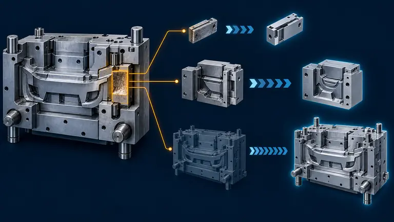
Conceptual illustration; not to scale.
A worn or damaged mold rarely presents a clean choice. A quick repair may restore shipments but leave little remaining life; a modification may correct the product yet create new maintenance risk; a replacement may protect the program but arrive after the immediate shortage. Choosing only by the lowest quotation can move cost into scrap, downtime, validation, or customer disruption.
Choose through a structured technical and program review. Contain current production, identify the failure mechanism, establish the tool’s actual condition and product revision, compare repair, modification, and replacement against required life, timing, validation, machine fit, ownership, and total risk, then approve a scoped path with measurable acceptance criteria. Immediate recovery and long-term tooling strategy may need to run in parallel.
Separate production containment from the tooling decision
The team first needs to protect conforming supply without allowing urgency to determine the permanent solution. A temporary repair can be appropriate, but it should be labeled, limited, and monitored rather than treated as restored design intent.
Quarantine suspect parts and define the traceability boundary. Identify affected cavities, dates, process conditions, and failure characteristics. Confirm available finished goods, work in process, resin, alternate cavities, service stock, and customer demand. If running fewer cavities, a longer cycle, additional inspection, or a temporary process could protect supply, obtain the required engineering, quality, and customer authorization before shipment.
Preserve failure evidence before polishing, welding, grinding, or replacing components. Photograph the condition, retain damaged parts and representative molded samples, and record machine alarms, process traces, maintenance history, part count, resin and additives, cooling flow, lubrication, and previous repairs. A broken pin may be the visible result of misalignment, galling, contamination, over-travel, poor support, or a sequence error; replacing the pin without finding the load path can repeat the failure.
Where the customer line is at risk, state the temporary inspection frequency, cavity restrictions, maximum authorized quantity, expiration time, and escalation trigger. This keeps emergency output traceable and prevents a temporary concession from becoming an undocumented normal process.
Create two timelines: the earliest controlled recovery and the durable tooling solution. They may converge, but management should see when an interim action consumes steel, time, or evidence needed for the permanent path.
Diagnose condition and failure mechanism before pricing options
Repair proposals are only comparable when they address the same cause and scope. Inspect the complete system around the failed feature, not just the damaged component.
Review forming surfaces, parting line, shutoffs, inserts, slides, lifters, guides, ejectors, support, alignment, hot runner, heaters and thermocouples, valve gates, cooling circuits, sensors, hydraulics, pneumatics, clamp interfaces, and corrosion. Compare component dimensions and clearances with available drawings and known-good records. Use appropriate nondestructive examination when cracking, weld integrity, or hidden damage is plausible and the consequence justifies it.
Map the defect to the molded part and process. Is flash caused by steel wear, mold deflection, clamp or support, contamination, or pressure? Is a dimension drifting because of cavity wear, cooling restriction, resin state, or measurement timing? Does galling come from hardness, finish, lubrication, alignment, or thermal growth? A technically honest diagnosis can conclude that more evidence is needed.
Classify the condition: isolated replaceable component; localized forming-surface damage; systematic wear or corrosion; outdated product geometry; repeated hot-runner or cooling failure; frame/alignment problem; or widespread loss of maintainability. Record tool age and shot history only when traceable. A nameplate estimate should not be presented as verified remaining life.
When repair is the defensible path
Repair restores intended function without deliberately changing the released product geometry. It is strongest when the failure is localized, the surrounding structure is sound, design intent is known, replacement components or a controlled restoration method exist, and the required life fits the solution.
Examples include replacing standardized wear components, restoring a damaged ejector system, repairing a leak, servicing a hot-runner component under the supplier’s instructions, clearing and validating a cooling circuit, or restoring a localized steel feature with an approved method. Welding or deposition may be possible, but base steel, hardness, heat treatment, crack risk, finish, texture, corrosion behavior, and future repairability must be considered. Follow qualified procedures and material guidance; do not use a generic weld assumption for every tool steel.
Define the repair boundary on a drawing or marked image. Specify components, materials, hardness or treatment where required, dimensions, surface condition, alignment, cooling and electrical checks, and parts to be replaced preventively. Include inspection after work, dry-cycle checks, leak and function tests, a molding trial, cavity-identified parts, and agreed dimensional or functional evidence.
Ask how the restored area will be inspected and serviced later. A repair that cannot be measured, disassembled, or repeated under controlled instructions may solve the immediate defect while making the next maintenance event less predictable.
Repair becomes weak when damage is widespread, the root load remains, interfaces are obsolete, records are unreliable, or multiple prior repairs have reduced correction options. A fast repair can still be approved as containment while replacement proceeds, provided everyone understands its limits.
When modification is required
Modification intentionally changes the mold or molding system to meet a revised product, correct a design or manufacturability issue, improve robustness, add traceability, change an interface, or support a new process condition. Because it changes the established state, it needs controlled engineering and approval.
Start with released change authority: updated CAD and drawing, engineering change, deviation, design approval, DFM decision, and customer-specific submission requirements. Identify affected dimensions, tolerance stacks, function, appearance, material flow, venting, cooling, ejection, steel strength, texture, and interchangeability. Do not let a tooling sketch silently become the product definition.
Assess whether the requested geometry is steel-safe. Removing steel from a cavity generally makes the corresponding external plastic feature larger; removing steel from a core generally makes the corresponding internal plastic feature larger. Actual correction direction depends on feature geometry and must be reviewed, as explained in steel-safe tooling for dimensional corrections. Adding steel through inserts, welding, or replacement may be required when the correction direction is opposite.
Modification is appropriate only if the mold has sufficient structural condition and usable life after the change. Check whether a new insert weakens support, a larger opening approaches shutoff limits, added cooling can be manufactured safely, or automation and mating components must change. Plan trials and revalidation around affected risks instead of assuming a small steel change requires no customer action.
Update the mold assembly, component drawing, cooling or wiring map, maintenance plan, spare list, and correction history after approval. The modified physical tool and the released record must not diverge again.
When replacement provides the better program outcome
A replacement tool is not automatically justified by age, nor ruled out by high initial cost. It becomes credible when continued repair cannot provide required life, quality, capacity, maintainability, safety, or revision flexibility within the program horizon.
Signals include recurring failures from a common structural cause, extensive corrosion or cracking, obsolete hot-runner or control components, poor cooling that cannot be corrected, frame or alignment damage, worn forming surfaces across many cavities, undocumented geometry that cannot support controlled changes, inability to fit available production equipment, or demand beyond demonstrated capability. Product redesign or localization may also make a new tool more efficient than repeated modification.
Estimate replacement as a program, not a mold invoice. Include design recovery, DFM, material and tool specifications, build, gages, fixtures, automation, trials, correction cycles, measurement, specified testing, capacity evidence, submission, packaging, inventory bridge, transfer or disposal, and launch support. Include the continuing risk and maintenance cost of the old tool during build.
Define whether the old tool remains production, backup, service, or scrap after release. Protect ownership and customer property, preserve records, and avoid destroying the only usable asset before the replacement is approved. A duplicate-tool comparison may be required if both tools will produce interchangeable parts.
Compare options with a life-cycle decision matrix
Use a scored matrix as a discussion aid, not an automatic answer. Weight criteria by the actual program consequence and attach evidence to every score.
| Criterion | Repair | Modify | Replace | Evidence to request |
|---|---|---|---|---|
| Time to controlled supply | Often shortest if localized | Depends on design/change approval | Usually longest | Detailed schedule and gates |
| Root-cause removal | Strong only if cause is addressed | Strong for defined design/process cause | Strong if new design resolves systemic cause | Failure analysis and design review |
| Remaining life | Limited by surrounding condition | Limited by base tool condition | Designed for stated demand and maintenance | Condition report and life assumptions |
| Product/change capability | Restores current intent | Implements controlled revision | Can incorporate broader redesign | Released data and change authority |
| Validation burden | Risk-based after repair | Based on affected change | New-tool/source approval normally substantial | Customer and quality plan |
| Total program cost | Low initial, potentially repeated | Moderate but scope-sensitive | High initial, potentially lower long-term risk | One-time, recurring and disruption cost |
| Reversibility | Varies by repair method | May consume correction steel | Old tool can remain until release | Steel review and transition plan |
Add timing against inventory coverage, program life, annual demand range, service obligations, alternate capacity, and customer approval. Run at least one downside scenario for a repeat failure or delayed qualification. Choose an interim and permanent path separately when that better protects the program.
Record confidence in the condition evidence as well as the score. An option supported by a complete inspection should not be treated as equally certain to one based on inaccessible steel, missing history, or an unconfirmed material specification.
Illustrative example: repeated flash at a slide shutoff
This illustrative example is not a customer case. An eight-cavity housing mold develops flash at two slide shutoffs. A local polish briefly improves parts, but flash returns. The program has two years of expected production and no approved backup tool.
Inspection finds wear on replaceable slide components, inconsistent support, and a cooling restriction near the affected area. The team compares three options. A component repair plus cooling restoration can recover production quickly and includes a trial and cavity dimensional check. A modification could redesign the slide support, but it needs engineering approval and carries schedule risk. Full replacement offers the longest life but cannot protect the immediate demand.
The approved plan repairs the components and cooling circuit under a defined shot-count and inspection trigger while engineering completes a structured slide modification. Replacement remains a contingency if the base-tool condition or modification trial fails. The plan records that the first repair is controlled containment, not proof of two-year life.
By separating supply recovery from the durable choice, the buyer avoids both an unnecessary immediate replacement and an endless sequence of undocumented polishing.
Evidence required before releasing the selected path
- released product and mold data, approved changes and affected-characteristic review;
- traceable failure samples, process records, maintenance, shot and prior-repair history where available;
- mold condition report with photographs, measurements, circuit and component findings;
- root-cause analysis and explanation of how the proposed work addresses it;
- itemized scope, materials, procedures, component sources, schedule, assumptions and exclusions;
- post-work inspection, dry cycle, leak, electrical, hot-runner and safety checks as applicable;
- trial plan, material, machine, process, cavity identification, measurement and functional acceptance;
- customer notification, submission, deviation, capacity and production-release requirements;
- maintenance, spare parts, monitoring trigger, warranty and remaining-life assumptions.
Require disposition of every open risk. “Trial successful” should mean the predefined evidence passed, not simply that parts came out of the mold.
Conclusion
Repair when damage is controlled, modify when released intent must change, and replace when the base tool cannot support the required life or robustness. Send AutoMoldingPro the part and mold data, defect evidence, tool history, demand horizon, machine details, inventory coverage, and approval requirements for an option review.