
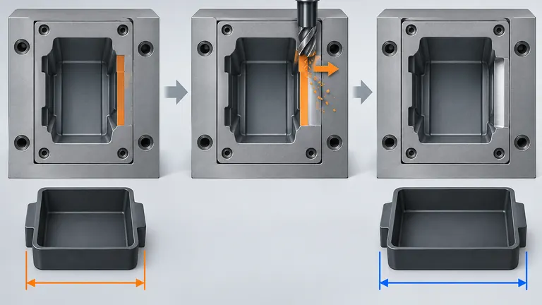
Conceptual illustration; not to scale.
The first molded parts often reveal a dimension that needs correction, but the correction is easy only when the mold was planned for the direction of change. A hole that must become smaller, a boss that must grow, or a profile that needs to move relative to a datum can require different steel actions. If the tool has no correction path, the team may face welding, insert replacement or a new component after the trial.
Steel-safe tooling means planning the initial metal so a likely product correction can be made by removing metal from the relevant mold surface, while preserving the function of the tool and the ability to verify the change. The direction is feature-specific: outside and inside dimensions, core and cavity surfaces, holes, bosses, shutoffs and locations must be analyzed separately. There is no universal stock amount that is correct for every feature.
This article covers correction strategy. It does not decide the part’s drawing tolerances; use the released drawing, datum scheme and function review for that decision.
Define what “steel safe” means for the feature
Why this matters: The phrase is often used as if metal always moves in one direction. In reality, a correction must be viewed from the molded plastic and then mapped to the cavity or core surface that creates it. A vague steel-safe note can create an opposite correction or an unintentional change to a neighboring feature.
The basic principle is to leave metal where a likely change can be made by removing it. Protolabs explains the relationship plainly: adding plastic to a part generally means removing metal from a mold, while removing plastic can require adding metal or remaking the tool. That principle is useful, but it does not replace a component-level mold review.
For an outside wall formed by a cavity, removing cavity steel usually enlarges the molded outside feature. For an internal hole formed by a core, removing core steel usually enlarges the molded hole. For a boss outside diameter formed by a cavity around a core, the correction direction must be checked against which surface is moved. For a boss inside diameter, the core controls the bore and the sign changes again. The same “remove steel” instruction cannot be applied to both sides without a feature map.
Location correction is more complex than size correction. Moving one surface or insert may shift a feature relative to datums but can also change wall thickness, shutoff fit, gate balance or an adjacent hole. If the part needs a position change, identify the steel component, datum reference, direction vector and secondary effects before machining.
Mark the design with three items: the molded feature, the steel surface that creates it, and the allowed first correction direction. Then mark whether the feature is critical, whether a replaceable insert is needed and what evidence will authorize a correction. A steel-safe condition is a planned option, not permission to remove metal without a measured finding and approved disposition.
Use a section or model mark-up to show the intended plastic change and the steel face that will be machined. A callout such as “leave steel safe” without a direction is incomplete. The mark-up should also identify whether the change is size, location, orientation or profile, and whether the feature shares a shutoff or datum with another characteristic. This prevents a convenient local machining operation from solving one measurement while creating a new interface failure.
Link correction direction to shrinkage and process assumptions
Why this matters: A T1 dimensional deviation may come from tool geometry, shrinkage, fiber orientation, packing, cooling, ejection, material state, measurement method or fixture restraint. A steel correction is appropriate only after the likely cause has been bounded.
Start with the material and process baseline. Confirm the exact resin grade, reinforcement, color, drying, machine, cavity, fill and pack conditions, mold temperature, cooling balance and ejection sequence. Compare the actual process with the assumptions used for the mold shrinkage compensation. A shrinkage estimate is a design input, not a guarantee that the part will land at nominal dimensions.
For reinforced resins, flow direction can create different movement along and across the flow path. A part may show a consistent location shift that steel removal at one face cannot correct without distorting the geometry. For flexible walls, a free-state measurement may not agree with a constrained assembly result. For moisture-sensitive materials, the sample state and elapsed time may be decisive. Validate the measurement first; ISO 14253-1 provides a framework for conformity decisions near limits with measurement uncertainty in view.
Separate systematic deviation from random variation. A consistent cavity-specific offset may support a local insert correction. A cavity-to-cavity spread or unstable process may require process and moldflow work before changing steel. A dimension that changes after storage may require a defined material state rather than a new cavity size.
Use a correction record that contains nominal, tolerance, actual result, datum setup, sample state, measurement uncertainty or method, cavity, process revision, suspected cause, proposed steel action, affected components, expected molded result and validation plan. The record should say whether the correction is approved, rejected, conditional or waiting for more data. Do not let a supplier infer the correction from a marked-up report.
Use the same sample state and datum setup when comparing the baseline and the corrected part. Keep cavity identity and process revision in the report. If the deviation is not consistent, pause steel work and investigate process or measurement variation. If the deviation is consistent but the proposed removal changes wall thickness or a mating clearance, review the adjacent characteristics before approving it. Steel-safe planning supports a correction; it does not make an uncertain diagnosis safe.
Plan core, cavity, insert and shutoff strategy
Why this matters: The ability to correct a feature depends on how the mold creates it. A monolithic cavity may be difficult to repair without visible weld or finish changes; a replaceable insert can localize the correction but adds interfaces and maintenance.
During mold design, map critical features to steel components. Prefer independent inserts when a feature is likely to move during development, needs a special material or requires future maintenance. However, an insert line can affect parting, flash, texture, cooling and alignment. An insert is not automatically safer than a solid block. The toolmaker should explain the tradeoff.
For cores and cavities, identify which surface can be safely machined and how much adjacent steel supports it. A dimensional correction may require removing material from a core, cavity or both to preserve wall thickness. A position change may require a new insert, a shifted insert pocket or a different datum strategy. For shutoffs, removing metal can increase flash or open a leakage path. For slides and lifters, movement and wear can change the result after machining.
Keep the correction strategy compatible with surface finish. A polished or textured surface may need a controlled re-polish or re-etch after machining. A cosmetic correction should identify the appearance limit and requalification check. For hardened or treated components, local grinding may be possible while milling, welding or heat treatment may not be. Ask the steel supplier or toolmaker for the authorized repair process.
The original mold drawing should identify steel-safe surfaces, nominal starting condition, correction limits, component serial or revision, and the inspection points that must be rechecked after machining. This does not mean adding arbitrary excess material. It means making a deliberate allocation where a likely change can be executed without compromising shutoffs, strength, cooling or finish.
Ask for the correction access at the design review: can the component be removed, supported, machined and inspected without disturbing a critical surface? Record the minimum remaining land, alignment features, cooling clearance and finish-restoration requirement. If the feature is likely to change after the first sample, an independent insert may be worth the additional interface. If the risk is low, a solid block may be simpler and more robust. The decision belongs in the mold design, not only in the quotation.
Use a correction-planning table
Why this matters: The table below is a pre-tooling planning tool. Populate it from the released product definition and the mold design; do not treat its direction examples as universal rules.
Fill the table from measured or explicitly assumed behavior, then confirm the plastic-to-steel sign, affected component, adjacent risks and evidence before any metal is removed.
| Critical feature | Expected T1 deviation or uncertainty | Mold surface/component | Planned correction direction | Secondary risk | Validation evidence |
|---|---|---|---|---|---|
| Mounting-hole diameter | Hole may be too small or too large after process baseline | Core pin or replaceable core insert | Confirm whether core removal enlarges the hole; do not assume | Fastener fit, draft and position | Gage/CMM result and mating fastener check |
| Boss outside diameter | Clamp or insert fit may require local size change | Cavity insert around boss | Map the cavity surface and desired plastic change | Wall thickness and sink | CMM plus assembly torque or fit check |
| Boss inside diameter | Insert or screw fit may be tight | Core pin or bore insert | Core removal generally enlarges plastic bore; confirm sign | Boss wall and strength | CMM plus authorized mating component |
| Connector opening location | Connector axis shifted relative to datum frame | Cavity/slide insert or opening insert | Define vector and affected steel faces | Gate, shutoff, wall and cable clearance | Datum-based CMM and functional connector check |
| Seating face profile | Flatness/profile result changes under fixture | Cavity or core seating insert | Remove steel only after free/constrained state is confirmed | Seal/fit and datum contact | Profile report under agreed fixture state |
| Clip retention feature | Engagement is too loose or too tight | Local core/cavity clip insert | Map whether plastic is added or removed at the hook | Force, breakage and draft | Functional insertion/retention test |
| Texture or cosmetic edge | Visual mismatch after tool correction | Replaceable cosmetic insert | Preserve texture boundary and repair limit | Witness, gloss and parting-line mark | Master-sample visual approval |
The table forces the team to state five things: the observed or expected deviation, the steel surface, the direction, the adjacent risk and the evidence. If the direction is uncertain, the correct status is “verify by section or supplier design review,” not a guessed allowance.
The expected deviation column should not be a guessed target. It can contain a measured T1 result, a documented shrinkage concern or a design-change scenario, but the source must be stated. The correction direction should be reviewed in a section view when the geometry is not obvious. The affected steel entry should name the insert, pin, cavity, slide or shutoff, and the validation entry should include both the critical feature and the neighboring features that could move.
Illustrative example: a hole is measured small and a second hole is measured in the correct size but wrong location. The first row may authorize a core correction after process stability is confirmed. The second row needs a position review and perhaps an insert move; enlarging the second core would not correct location. The table keeps those actions separate and gives the next sample a clear acceptance plan.
After the correction, compare the original result, predicted movement and actual movement. If the result differs, record whether the cause was shrinkage, process, fixture, measurement or machining. Keep a component drawing mark-up that shows the metal change and the surfaces protected from machining. The next correction should use the new released baseline, not an informal target from the previous meeting. This is particularly important when a feature shares a datum or shutoff with several other characteristics.
Sequence corrections from evidence to release
Why this matters: Correction order matters because one change can hide another. Start with measurement-method confirmation and gross molding stability. Then address parting-line flash, short shot or ejection distortion before fine dimensional correction. Next address systematic geometry and location issues, followed by cosmetic finish and secondary features.
Use cavity-by-cavity and component-by-component evidence. A correction based on pooled data can make one cavity pass while another moves out. The toolmaker should identify the affected cavity, insert and feature. Recheck adjacent dimensions, wall thickness, shutoff, cooling and ejection after machining. A correction is not complete when the target value moves; it is complete when the affected feature and its dependencies remain acceptable.
For a local insert, record the pre-machining measurement, metal removal or added component, surface restoration, inspection and new sample. For welding or heat treatment, record the process, distortion risk and requalification scope. For a design revision, stop the correction and obtain the required customer disposition before cutting steel. Do not use steel-safe language to bypass product-change approval.
Illustrative example: an exterior bracket’s mounting hole is measured undersize in a stable process. The core pin controls the hole. The correction plan confirms that removing steel from the core will enlarge the hole and checks the adjacent wall and draft. A second hole is shifted relative to the bracket datum; it is not corrected by enlarging the pin because that would change size, not location. The supplier proposes a replaceable insert with a controlled position change, then rechecks both holes, the bracket fit and the cosmetic side.
Schedule the correction as a gated activity. The published T1 sample approval and production-release guide explains why a correction must be linked to an approval decision. The correction record should feed the next T1 or pilot plan, not sit only in an email thread.
Use a correction meeting record that captures the decision and the reason. The toolmaker should show the proposed metal change, the product effect and the recheck. Design or customer quality should approve changes that alter a functional requirement. After machining, inspect the component before assembly and inspect the molded result after the same process and state used for the baseline. Preserve both results so a later change can be traced to the correct tool revision.
Maintain a durable modification record
Why this matters: Every steel correction changes the history of the tool. Maintain a versioned mold drawing, component revision, reason for change, approval, actual machining, surface restoration, inspection result, sample identity and release status. Link the record to the product drawing revision and material/process revision.
The record should distinguish temporary development changes from released production changes. A trial-only insert may be useful for learning but should not be treated as the final production tool. If the customer approves a deviation, state the scope, expiry or follow-up requirement. If a correction is rejected, record that the steel remains at the original state and why.
Before production release, check that the steel-safe plan did not create a hidden risk: reduced shutoff land, insufficient support, altered cooling, weakened insert, mismatched texture, new flash or a changed datum. Preserve the original baseline so repeat-order checks can distinguish a process shift from a prior correction. This is especially important for repeat automotive molding consistency.
The record should identify the person who authorized the work and the person who verified the result. Add photographs or section views only when they explain the component change; do not use a photograph as a substitute for a dimensional report. When a tool is transferred, include the modification history with the incoming inspection so the receiving team knows which steel is the released baseline. When a second-source or repeat-order process is developed, use the released tool revision rather than an old T1 condition as the comparison point.
Also identify the person who authorized the work and the person who verified the result. Add photographs or section views only when they explain the component change; do not use a photograph as a substitute for a dimensional report. When a tool is transferred, include the modification history with the incoming inspection so the receiving team knows which steel is the released baseline. When a second-source or repeat-order process is developed, use the released tool revision rather than an old T1 condition as the comparison point. Add the modification date, reason, affected drawing revision and disposition of removed steel so future maintenance does not reintroduce an obsolete component. Keep the old component identity, new component identity, heat-treatment or finish record, inspection result and customer disposition together. If the tool is repaired again, the next technician should be able to tell which surface is production-approved and which surface is only a development condition.
Conclusion
Plan steel-safe corrections feature by feature. Map the molded result to the core or cavity surface, confirm shrinkage and measurement assumptions, choose inserts where they genuinely localize risk, and record each correction with adjacent checks and approval. Never apply one fixed allowance or one correction direction to every dimension.
References
- Protolabs, A Guide to Steel Safe and Metal Safe Injection Molding — metal-removal principle and feature-by-feature correction planning.
- ISO, ISO 14253-1:2017 — measurement uncertainty and conformity decisions near limits.
- ASME, Dimensioning and Tolerancing / Y14.5 — datum and geometric-tolerance language used to define functional features.
- AutoMoldingPro, T1 Sample Approval vs Production Release — related published article on approval status.