
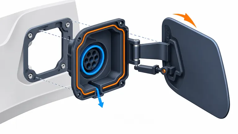
Conceptual illustration; not to scale.
The visible charging-port housing and flap sit at the intersection of body styling, user handling, weather exposure, actuator motion, sealing, and a high-voltage inlet assembly. A plastic part can meet its own dimensions and still bind, rattle, leak, misalign with the body opening, or obstruct the charging connector.
Define the molded-part RFQ from the complete interface chain: vehicle body, bezel or pocket, charging inlet, flap, hinge, actuator, seals, drain path, indicator, fasteners, and service motion. Select materials and mold details for the stated exposure and validation plan. Do not treat the plastic housing or flap as approval of the charging system.
Establish the component boundary and assembly sequence
Start by naming exactly what the supplier will make. “Charging port housing” may refer to a body-mounted pocket, inlet carrier, trim bezel, rear cover, pin holder, protective flap, or an assembled module. List every molded component, purchased insert, seal, spring, hinge pin, actuator, lamp or sensor interface, and fastener. Assign responsibility for molding, procurement, assembly, testing, and final system validation.
Provide a controlled assembly model with body opening, charging inlet envelope, connector mating path, cable exit, actuator sweep, flap opening, and service access. The inlet may be fixed before or after the pocket is mounted; that sequence changes tool access, clip design, tolerance stack, and mistake-proofing. Define the datum strategy from vehicle attachment through the visible gap and charging interface. Styling surfaces and the connector axis may be controlled by different subassemblies, so their relationship needs an explicit stack.
TE Connectivity’s charging-inlet flap assembly demonstrates that commercial products can include independent AC/DC flaps, optional indicators, defined materials, opening configurations, and product drawings. Use such product documentation to understand interface categories, not to copy dimensions or claim the same ratings. The actual inlet and flap selected for the customer program govern the mating data.
Map the assembly sequence in both directions. Show how clips engage, seals are installed, the actuator connects, cables route, and the module is removed for service. Identify where an operator could misorient a component or partially seat a latch. A retention feature that is inaccessible after vehicle assembly needs robust confirmation or an alternate service plan.
Translate exposure into part-level requirements
The port area may see sunlight, rain, road spray, wash pressure, dust, ice, cleaning chemicals, temperature cycling, user impact, and repeated opening. The exact exposure depends on vehicle location, door design, regional climate, and the surrounding seals and drains. Do not assign a generic IP rating to one loose plastic part. Ingress protection belongs to a defined enclosure and test configuration.
ISO 20653:2023 specifies IP-code designations and tests for enclosures of road-vehicle electrical equipment. The buyer should state the required enclosure boundary, mated or unmated condition, installed seals, vents, drain state, mounting, preconditioning, and test responsibility. A supplier can mold the pocket and flap to agreed dimensions, but the assembled enclosure must be tested as specified by the program.
Separate appearance exposure from electrical protection. The flap may require color and gloss retention, scratch resistance, low-temperature impact, hinge durability, and gap consistency. The inlet carrier may prioritize stiffness, heat aging, electrical insulation, and dimensional stability. A rear cover may need cable strain management and sealing. LANXESS’s charging-inlet design concept describes using different material solutions for different components, integrated fastening, seal flexibility, and cable retention. It is one supplier’s concept and test basis, not a universal vehicle requirement.
Create an exposure matrix with condition, affected component, function, conditioning sequence, and acceptance criterion. Include water and dust only where the system requires them; include UV only for exposed surfaces; include fluid splash based on actual vehicle location. Then identify which evidence is resin data, molded-part testing, assembled-module testing, or vehicle validation.
Review flap motion, hinge, actuator, and sealing together
Define the full motion envelope: closed position, opening direction, maximum angle, detent, spring or motor force, manual override, connector clearance, and body-panel clearance. Add ice or contamination allowances only if the customer defines them. The mold supplier needs the mating surfaces and load cases, not just the nominal flap CAD.
For a pinned hinge, review boss thickness, pin fit, bearing length, assembly direction, wear, and retention. For an integral hinge, confirm that the selected grade, flow direction, hinge geometry, processing, and expected cycles support the concept; many engineering materials used for stiff carriers are not interchangeable with living-hinge materials. For an actuator interface, define shaft or link envelope, torque, end stops, positional feedback, backlash, and failure position. The plastic stop should not unintentionally carry loads intended for the actuator or body bracket.
Seal design requires controlled lands, compression, joint continuity, fastener or clip spacing, and tolerance analysis. Warpage of a long rim can reduce local compression even when point dimensions pass. Drainage must have a defined downhill path in the installed vehicle orientation and should not discharge onto sensitive components. A cosmetic shutline is not automatically a water seal.
Use an interface-and-motion review before tool release. Animate the full assembly, mark interference clearance through tolerance extremes, identify flexible clips and stops, and specify the measuring condition. Plan functional gauges or assembly fixtures around the body datums and inlet axis. If the flap is supplied separately from the inlet, identify who performs the final motion and ingress validation.
Choose material and mold architecture for the actual part
Material screening should consider component function, exact temperature range, UV and weathering, moisture and hydrolysis, impact, stiffness and creep, chemical exposure, dimensional stability, appearance, flammability or electrical requirements, color, and processing. TE’s flap product page lists PBT for a specific commercial product; LANXESS describes polyamide and polyester solutions in its concept. Neither means “PBT” or “PA” is sufficient as an RFQ specification.
Request grade-specific TDS, processing guidance, color information, and applicable listings. Evaluate properties at the thickness, temperature, moisture state, aging, and test method relevant to the design. If the component touches live parts, customer electrical and flammability requirements may differ from an outer cosmetic flap. Avoid transferring a material rating to the complete assembly.
Mold design should protect the visible surface and motion interfaces. Review gate location, weld lines at hinge or clip roots, sink near bosses, venting at thin ends, parting-line witness, texture draft, ejector marks, and cooling around long rims. Large pockets may warp from differential wall thickness, asymmetric cooling, or fiber orientation. Define steel-safe corrections on gap, latch, and seal features only after confirming the direction in which steel removal changes the plastic feature.
Consider insert loading, seal assembly, decoration, indicator windows, and automation early. If a transparent light guide is a separate component, treat material, gate vestige, optical surface, and assembly cleanliness separately. If the customer wants a painted or textured flap, identify substrate, pretreatment, color, gloss, adhesion, and masking requirements rather than assuming molded color alone.
Build the RFQ and validation matrix
| Area | RFQ input | Evidence before release |
|---|---|---|
| Vehicle/body interface | Mounting datums, gap/flush targets, panel and service envelope | Dimensional stack and installed fit check |
| Charging interface | Inlet model, mating path, cable exit and keep-outs | Assembly and connector-clearance verification |
| Motion | Hinge, actuator, stops, forces, cycles and manual operation | Conditioned motion and durability plan |
| Exposure | Temperature, UV, water/dust, chemicals, ice and impact as applicable | Grade data plus component/module tests |
| Sealing/drainage | Boundary, seal, compression, vents, drains and test configuration | Assembled enclosure test to customer requirement |
| Appearance | Color, texture, gloss, witness and no-contact zones | Approved appearance method and samples |
| Production | Volumes, cavity plan, target press, assembly and traceability | Capacity and cavity-specific control plan |
For each row, identify who owns the final decision: molded-part supplier, inlet or actuator supplier, module integrator, body engineering, validation laboratory, or vehicle customer. Then link the RFQ input to a drawing characteristic, test method, sample condition, and acceptance authority. This prevents a supplier’s dimensional report from being mistaken for proof of the complete port assembly’s ingress, durability, or vehicle fit. It also exposes missing interface data before mold steel is cut, when the team still has practical options to change a locating scheme, seal land, latch, gate, or inspection method.
Illustrative example: a buyer supplies only the outer flap CAD and asks for an “IP67 charging-door quote.” The molder cannot determine the enclosure boundary, inlet, seals, pocket, body mounting, actuator, or test condition. A useful response is not a guessed certification price. The buyer should provide the assembly model, interface drawings, exposure matrix, seal concept, material basis, motion requirements, and responsibility for module testing. The supplier can then quote molded parts and agreed assembly evidence without claiming approval of the complete charging system.
Prepare the STEP assembly, 2D critical features, inlet and actuator interfaces, exact material or property basis, annual demand, appearance map, exposure matrix, and validation responsibility. AutoMoldingPro can review molded charging-port parts within its EV electrical component application scope; send the controlled package through the request-a-quote page.