
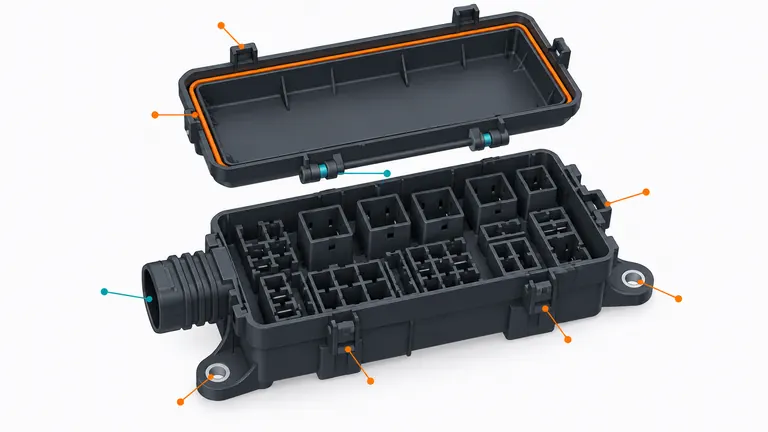
Conceptual illustration; not to scale.
A fuse or relay box housing can be moldable and still fail at assembly: a terminal does not seat, a lid rattles, a clip fractures, a busbar loses location, or a mounting foot shifts under harness load. These risks are controlled by the complete interface definition, not by naming a polymer family or adding a generic flammability callout.
For an effective RFQ, define the housing, lid, terminal and busbar interfaces, locks, mounting, sealing or drainage concept, service actions, loads, environment, exact material basis, appearance, identification, and component-level validation. Keep material test data, molded-subcomponent evidence, assembled-box tests, and vehicle-system approval as separate layers.
Map every interface before reviewing the plastic geometry
Begin with an interface drawing or annotated assembly model. The plastic base may locate fuse terminals, relay terminals, busbars, secondary locks, seals, grommets, brackets, printed circuits, covers, and harness exits. The lid may need to clear installed devices, compress a seal, retain a label, provide service access, and return to a defined position. Mounting feet and studs transfer vehicle vibration and harness loads into the housing.
For each interface, identify the mating part number or controlled envelope, insertion direction, required clearance, retention method, datum relationship, service sequence, and acceptance test. A nominal cavity shown in CAD is not enough when terminal suppliers control blade, latch, shoulder, or seal geometry through separate product drawings. TE Connectivity’s automotive power-distribution catalog illustrates how fuse-and-relay products are defined by position count, terminal family, material, temperature class, sealing state, and application specification. Those values describe specific TE products, not universal requirements for every box.
Create a tolerance stack from the assembly function backward. Terminal seating may depend on a floor, shoulder, lock window, and secondary lock. Lid engagement may depend on hinge center, latch hook, gasket land, and housing rim. Mounting may depend on several bosses and the body bracket. Avoid tightening unrelated dimensions; control the datums and features that locate the actual interface.
Also identify service forces. Determine whether a fuse, relay, lid, or connector must be removed by hand or tool, how often, and in which temperature state. A latch that survives one room-temperature assembly may not meet repeated service or cold-impact requirements. Define the component and assembly evidence instead of relying on a visual fit check.
Treat clips, locks, hinges, and lids as working mechanisms
For each molded clip, document the beam length, thickness, root radius, draft, deflection direction, permitted strain basis, engagement depth, lead-in, over-travel stop, and tool-release direction. Determine which surface provides retention and which only guides assembly. The mating edge, tolerance stack, material condition, temperature, and assembly rate all influence force. A generic “snap fit” note cannot establish insertion or retention performance.
Review the tool action with the mechanism. A hook may require a side action, lifter, shutoff, or compliant stripping path. Draft added for release changes engagement geometry. An ejector under a flexible arm may deform it before the part is stable. A weld line across the clip root may affect performance, but its presence alone does not quantify strength. Gate, vent, and flow decisions should keep functional regions reviewable and establish what trial evidence will confirm them.
Lids introduce their own stack. Define hinge type, opening angle, detent, latch sequence, seal compression if applicable, anti-rattle features, finger access, and service clearance around installed fuses and relays. For a living hinge, the resin, flow direction, thickness transition, and molding history are central; do not substitute a living hinge automatically for a pinned hinge. For a separate pin or actuator, include purchased-component tolerances and assembly mistake-proofing.
Do not assume every fuse box is sealed. TE’s product portfolio includes both sealed and unsealed arrangements, and individual products list different position counts and environmental ratings. If sealing is required, identify the complete sealing boundary, mating connector states, vents or drains, fasteners, gasket material and compression, and required assembled test. A housing resin or lid alone cannot establish an ingress-protection result.
Select material from the requirement set, not a family name
The RFQ should state an exact approved grade or a property-and-validation specification that allows alternatives to be evaluated. Relevant inputs may include continuous and peak temperature at the location, heat aging, impact at low temperature, stiffness and creep under terminal or mounting loads, dimensional stability, moisture and hydrolysis exposure, chemical contact, electrical insulation, tracking resistance, flammability, color and laser marking, UV exposure, and molding flow for thin features.
BASF identifies flame retardancy, electrical isolation, heat aging, and colorability as considerations for eMobility housings, fuse boxes, connectors, and inlets. Its application pages also distinguish polyamide, PPA, PBT, and other grade families. This is a screening direction, not permission to interchange grades. Glass content, flame-retardant package, color, conditioning state, thickness, and test method influence published properties and molded behavior.
Treat UL 94 correctly. UL explains that its small-scale tests characterize plastic materials under defined specimen conditions and that acceptability of the material in an end product is determined in the end-product context. A V-0, V-1, V-2, or HB designation therefore needs the grade, color, thickness, and listing conditions. It does not certify the complete fuse box, vehicle circuit, or customer application. Use the UL explanation of rating limitations to keep this boundary clear.
Ask for the manufacturer’s current TDS and, where relevant, a UL Product iQ record for the exact grade and color. Then define incoming resin identification, drying and storage, regrind restrictions, lot traceability, and change control. Material approval should also consider molded-component tests: latch force, terminal retention, dimensional stability, aging, exposure, and assembly. The right grade is the one shown to meet the actual component and system requirements under agreed conditions.
Design the mold and validation plan around critical interfaces
Thin terminal cavities, deep walls, multiple clips, and large lid rims can create competing flow, cooling, ejection, and warpage risks. Review gate location against weld lines at clip roots and terminal windows, air traps near last-to-fill pockets, packability of mounting bosses, and visible gate vestige. Provide venting and ejection access without marking sealing lands or terminal datums. Cooling should address thick mounting features and long perimeter walls that can distort lid fit.
Decide cavity count from annual demand, part size, press compatibility, and cavity-to-cavity control. Each cavity should be identifiable when dimensional or functional results may differ. Use steel-safe planning only where the correction direction is understood. For a terminal window, removing steel may enlarge one dimension but reduce retention; for an outside envelope, the relationship is different. Record the intended correction path before tool release.
Build validation in layers. First confirm molded-part dimensions, appearance, material identity, and feature condition by cavity. Then assemble actual terminals, locks, seals, lids, busbars, and fasteners using the intended process. Measure insertion, retention, latch, hinge, and mounting performance under specified conditioning. Finally, complete customer-defined electrical, environmental, ingress, vibration, thermal, and vehicle-level evaluations. Passing a resin test or loose-part dimensional report does not replace the assembled-box or system tests.
AIAG’s quality core tools provide connected planning concepts for FMEA, Control Plan, MSA, SPC, and PPAP, but the submission content and acceptance thresholds remain customer- and program-specific. Define which characteristics require capability evidence, which gauges need measurement-system study, and what change triggers revalidation.
RFQ checklist for housing and lid parts
| Input | Minimum useful detail | Why the molder needs it |
|---|---|---|
| Product definition | STEP, 2D drawing, datums, appearance and revisions | Controls tool geometry and inspection |
| Mating interfaces | Terminal, relay, fuse, busbar, seal, bracket and connector data | Establishes location, fit and retention |
| Mechanisms | Clip, lock, hinge, lid, service sequence and force criteria | Drives material, tool action and testing |
| Environment | Temperature, fluids, moisture, dust/water, UV and vibration conditions | Supports grade and validation planning |
| Electrical/material | Exact grade or approved property specification; color and traceability | Prevents generic resin substitution |
| Production | Annual and peak volume, cavity expectations, target press and automation | Supports tool and capacity design |
| Validation | Component, assembly and system tests with conditioning and acceptance | Separates evidence layers |
| Packaging | Contact restrictions, cleanliness, orientation, quantity and labels | Protects clips, rims and interfaces |
An illustrative example: a buyer requests a black “PBT fuse box” but supplies no terminal drawings or lid-force criteria. One supplier prices a simple open housing; another assumes secondary locks, cavity-specific gauging, and a sealed lid. The quotes are not comparable. Adding the terminal envelopes, latch forces, gasket land, service temperature, exact grade basis, and validation responsibility allows both suppliers to quote the same part and evidence package.
Prepare the controlled assembly data, exact material requirement, annual demand, critical interfaces, and validation matrix before seeking production pricing. AutoMoldingPro’s EV and automotive electrical component page outlines the application boundary; use the RFQ page to submit the housing and lid package for manufacturability assessment.