
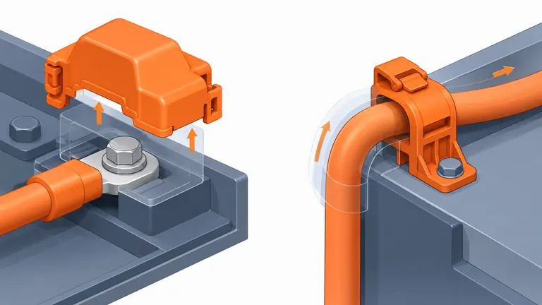
Conceptual illustration; not to scale.
A terminal cover or cable support may look like a simple molded part, yet its function depends on the live-part envelope, service access, cable movement, fastener stack, neighboring conductors, temperature, fluids, and fault strategy. Calling out an orange flame-retardant polymer does not define electrical protection or prove the assembled battery connection is safe.
Build the RFQ from the electrical-system requirement down to the plastic subcomponent. Provide the voltage-class context, protected and accessible zones, terminal and cable geometry, assembly and service sequence, loads, environment, material and color controls, and validation responsibility. Keep resin properties, molded-part tests, connector or joint tests, battery-subsystem tests, and vehicle approval distinct.
Define what the plastic part must prevent and control
Identify the protected object: bolted terminal, busbar end, connector, service disconnect, cable lug, splice, sensor lead, or routing segment. Mark conductive envelopes, fastener heads, tools used in service, finger or probe access zones, neighboring grounded structures, and all assembly positions. Define whether the cover is installed before energization, removed during service, captive, replaceable, or single-use.
ISO 6469-3:2021 covers electrical safety requirements for voltage-class-B circuits in electrically propelled road vehicles, including protection against electric shock and thermal incidents. The complete standard and customer specifications should be used by the responsible system engineers. The injection molder needs the resulting part-level requirements; it should not invent electrical clearances or claim compliance from geometry alone.
Translate system intent into measurable features. Examples include a required protective envelope, minimum engagement, latch retention, installation confirmation, tool-access restriction, fastener clearance, cable bend support, strain-relief position, and keep-out around seals or cooling paths. If creepage or clearance is controlled, supply the governing voltage, pollution/environment assumptions, material group or tracking basis, surface path, and customer calculation. Do not provide a bare distance without the standard and conditions that produced it.
Cable supports have a different primary function from terminal covers. They control routing, bend radius, relative movement, abrasion, and load transfer. Define cable construction, diameter range, mass, stiffness, exit direction, clamp spacing, installation force, vehicle motion, vibration, and thermal growth. A support that holds a static CAD cylinder may overload the cable or terminal when the real harness moves.
Resolve interfaces, assembly state, and service behavior
Provide full mating geometry for terminal, fastener, busbar, cable lug, connector, bracket, seal, neighboring cover, and enclosure. The tolerance stack should start from the functional datum—often the conductive joint or battery structure—and end at the protective surface. If a cover clips to a terminal housing but is located by a remote bracket, both chains must be controlled.
Define assembly direction and error states. Can the cover appear seated while one latch is open? Can it be installed before the fastener reaches torque? Can the wrong cable size fit? Does a cable clip damage insulation during insertion? Use poka-yoke features only when their function can be measured. Add a positive seating indicator or inspection access if the assembly process needs one.
Service requirements influence material and feature design. State the number and temperature range of permitted removals, required tool, release force, access with gloves, and treatment after damage. A snap fit may be appropriate for one-time assembly but not repeated field service. A screw may improve retention but introduce loose-part and tool-access concerns. A hinged cover can remain captive but adds fatigue and packaging exposure.
ISO 20076 defines test methods for certain voltage-class-B connectors and explicitly notes that connector safety features depend on the connector and vehicle architecture; its scope does not apply to charging inlets and does not make it a universal terminal-cover specification. Use it as evidence that insertion, locking, tensile, insulation, and environmental questions belong to controlled assemblies, then select only the customer standards applicable to the actual component.
Specify the exact material evidence required
Material inputs may include dielectric behavior, tracking resistance, flammability, temperature aging, moisture and hydrolysis resistance, chemical exposure, impact, stiffness, creep, vibration, color stability, laser marking, and moldability. The priority depends on whether the part is inside a sealed battery enclosure, exposed underbody, near a heat source, removable in service, or carrying cable loads.
BASF describes electrical insulation, flame retardancy, hydrolysis resistance, colorability, and cable-management functions as eMobility material considerations. Its portfolio includes different PA, PPA, PBT, TPU, and other grades. Select by exact grade data and component validation; do not treat a polymer acronym as a performance guarantee.
For flammability, request the grade, color, tested thickness, and listing conditions. UL explains that a Recognized Component material is evaluated under stated conditions and that acceptability is determined in the end product. A UL 94 rating cannot by itself approve the cover, terminal joint, battery module, or vehicle. The same caution applies to comparative tracking index and dielectric data: specimen results support material screening but do not replace the geometry, aging, contamination, and assembled test.
Color can be safety-relevant when the customer uses orange for high-voltage identification, but define the approved color target, viewing and aging method, resin/colorant combination, and change control. Pigment and flame-retardant packages may affect properties and processing. Require material-lot traceability, drying and storage controls, regrind restrictions, and supplier notification for formulation or manufacturing-site changes.
Design the mold and inspection around protection features
Deep shrouds, thin walls, latches, cable clips, and long creepage paths can be difficult to fill, vent, cool, and eject. Review gate and weld-line locations away from highly strained clip roots where practical. Check venting at terminal shrouds, sink around mounting bosses, parting lines across protective surfaces, and ejector witness in mating areas. If the material is glass-filled, consider orientation and warpage across the protection envelope.
Dimensional inspection should reproduce the functional state. A flexible cover measured loose may not represent the installed protective envelope; a cable support clamped in a rigid gauge may hide creep or latch weakness. Define free-state dimensions, restrained or assembled checks, conditioning, datums, and functional gauges. Identify cavities and link retention or dimensional data to each cavity until pooling is justified.
Plan molding validation separately from electrical-system validation. The molder can confirm resin identity, process traceability, dimensions, appearance, latch forces, assembly fit, and agreed conditioning. The customer or responsible test organization may then evaluate electrical protection, temperature rise at the joint, dielectric performance, ingress, vibration, mechanical shock, chemical exposure, and system faults. Assign sample quantities, fixtures, test sequence, and acceptance authority.
Packaging must protect clips, shrouds, clean contact-adjacent surfaces, and safety color. Prevent parts from nesting so tightly that latches deform or operators damage them during separation. Define orientation and lot labels. If cleanliness near conductive joints matters, specify the contamination limit and verification method rather than saying “clean parts.”
RFQ evidence matrix
| RFQ area | Information to provide | Evidence to request |
|---|---|---|
| Electrical context | Voltage class, protected zones, access condition and governing customer requirements | Requirements trace from system to part |
| Interfaces | Terminal, busbar, fastener, cable, bracket, enclosure and service tools | Controlled CAD/drawings and tolerance stack |
| Cable loads | Cable size, stiffness, bend, routing, vibration and thermal movement | Support-load and assembly test plan |
| Material | Exact grade or property specification, color and change controls | TDS, applicable listing and incoming controls |
| Molded part | Datums, protective surfaces, clips, appearance and cavity ID | Dimensional and functional control plan |
| Validation | Conditioning, latch/service, environmental and electrical test ownership | Layered validation matrix and acceptance authority |
| Packaging | No-contact zones, nesting limits, cleanliness, quantity and labels | Approved packaging specification |
Use the matrix to separate five evidence layers: resin supplier data, incoming-material control, molded-part conformance, assembled-joint or harness testing, and battery or vehicle validation. Put the responsible organization and approval document beside each layer. When a requirement is still unknown, record it as an open input with a decision date; do not replace it with a convenient supplier assumption. At quotation comparison, normalize whether each bidder includes gauges, conditioning, retention fixtures, assembly samples, electrical testing, and customer submission support. A lower price may simply exclude a validation layer that another supplier has made visible.
Illustrative example: a buyer requests a “V-0 orange battery terminal cap” and supplies only the cap CAD. The supplier cannot establish the conductive envelope, voltage-class requirement, access probe, fastener tool, cable motion, color standard, grade thickness, or system test. The correct next step is to obtain those inputs and quote the molded part against a defined validation layer—not to promise battery-system compliance.
Send the complete interface model, 2D critical controls, governing customer requirements, exact material or property basis, annual volume, assembly sequence, service state, environmental profile, and validation matrix. AutoMoldingPro can assess the molded cover or cable-support scope through its EV electrical components page and request-a-quote form.