
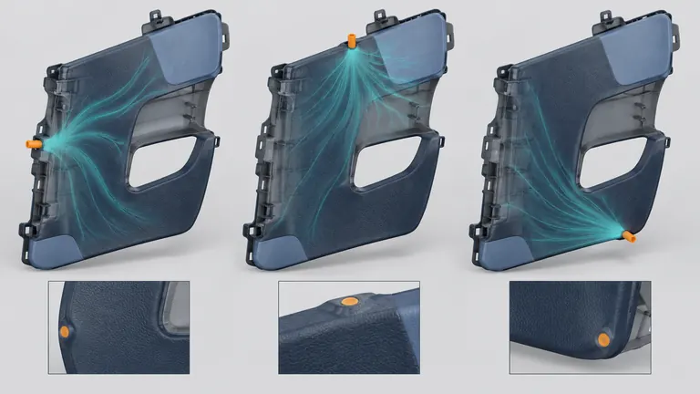
Every injection-molded part needs a material entry point, but an automotive cosmetic surface may not tolerate the resulting witness, blush, flow pattern, or trimming variation. Hiding the gate without considering fill and packing can create a less visible vestige and a worse part.
Approve gate location by balancing appearance zones with flow length, pressure, packing, weld lines, air removal, orientation, tool access, trimming, and service. Define the permitted vestige with a measurable profile or approved boundary sample and a viewing method. “Gate on the non-show side” is not a complete acceptance criterion.
Map appearance, function, and assembly constraints before choosing a gate
Gate selection starts with the product definition, not a preferred gate type. The team needs to know where a mark can exist, where it can be trimmed, and what other risks moving the gate creates.
Create an annotated zone map on the controlled CAD model. Mark direct and indirect show surfaces, gloss and grain boundaries, sealing faces, clip and screw interfaces, datum simulators, adhesive or paint areas, label locations, operator touch points, and surfaces hidden after final assembly. Include adjacent components because a gate that is hidden on the loose part may become visible through a gap or may interfere with assembly.
Define the visual context: installed orientation, normal viewing distance and angle, lighting, color, texture, and customer appearance standard. A small raised witness can catch a highlight on a glossy surface but be unobtrusive in a recessed, textured area. Conversely, locating a gate in a deep texture can complicate trimming and grain repair.
Functional restrictions can be stricter than appearance. Keep the gate and trimming operation away from sealing edges, snap engagement, bearing surfaces, electrical interfaces, and dimensional datums unless the design specifically accommodates them. Consider handling: can the runner be separated automatically, or will a manual cutter approach a fragile wall? Where do trimmed fragments go? Can a remaining sharp edge contact wiring or an operator?
Ask the mold supplier to return at least two feasible gate concepts when tradeoffs are significant. Each proposal should identify gate type and location, fill rationale, expected vestige, runner or hot-runner architecture, trimming method, maintenance access, and correction options. Protolabs’ cosmetic-design guidance notes that resin entry and flow affect appearance and that gate placement is a compromise requiring customer input (Protolabs cosmetic design guide). The project’s resin, geometry, and customer criteria remain decisive.
The zone map becomes the shared approval record for design, tooling, quality, and assembly teams.
Compare gate concepts by molding consequences, not vestige size alone
A gate is part of the feed and packing system. Its size, type, location, and freeze behavior affect how the cavity fills, how pressure reaches thick regions, where flow fronts meet, and what orientation or residual stress develops.
Review flow length and wall transitions from each candidate location. A gate into a thicker, structurally supported region may fill robustly but leave a visible witness. Moving it to a hidden thin edge may increase pressure, hesitation, shear, or early freeze. Multiple gates can shorten flow distance but create weld lines and require balancing or valve sequencing. A direct hot tip can remove a cold runner and centralize flow, but it creates a circular witness and adds thermal-system cost and maintenance.
| Gate concept | Potential benefit | Evidence and risk to review |
|---|---|---|
| Edge or tab gate | Accessible, adaptable, often tolerant of filled resin | Trim witness, runner waste, flow orientation, parting-line space |
| Tunnel/submarine gate | Automatic separation and hidden-side entry | Gate break, debris, core strength, vestige consistency |
| Hot-tip thermal gate | No cold runner and compact direct entry | Visible blush/witness, thermal history, gate freeze, maintenance |
| Valve gate | Controlled opening and potentially cleaner vestige | Alignment, sequence, controls, wear, shutoff quality |
| Multiple gates | Shorter flow paths or controlled filling | Weld lines, balance, valve timing, added hardware |
Use simulation when the consequence warrants it, but audit inputs and assumptions: actual resin data, geometry revision, gate dimensions, mold temperatures, process constraints, and analysis objective. Simulation can compare fill pressure, temperature, shear, air traps, weld locations, and packing tendency; it cannot by itself approve a customer’s subjective appearance.
Protolabs describes tab, hot-tip, and pin/tunnel approaches and explicitly notes that gate choice and location trade vestige against other molding issues (Solving Gating Problems). Do not copy its proprietary dimensional examples into a different resin and process as universal limits.
Score concepts against product function, appearance, process window, tool complexity, maintenance, automation, and future change risk. Record why the selected compromise is preferable and what trial evidence must still confirm.
Specify the gate witness and trimming result in an inspectable way
“Minimal gate vestige” cannot be measured or consistently judged. The drawing or appearance specification should define what surface condition is allowed and how the supplier will verify it.
Choose the appropriate control: maximum projection above a defined local surface, maximum depression, permitted breakout or whitening, edge contour, prohibited sharpness, trim boundary, or customer-approved limit sample. A profile or flushness requirement needs a datum or local reference and a measurement method that works on the textured or curved surface. Avoid demanding a precision number that the proposed method cannot resolve.
For visual criteria, define lighting, viewing angle and distance, evaluation time after molding or conditioning, color, texture, and whether the part is assessed loose or assembled. Use approved boundary samples when the requirement includes grain disturbance, blush, stress whitening, or a complex three-dimensional witness. Identify sample revision, cavity, material, date, storage, and approving authority so the reference does not drift.
Specify trimming method and control. Manual cutting introduces tool-angle and operator variation. Automatic de-gating can tear the gate if geometry or resin behavior is unsuitable. Machining can improve control but adds fixtures, chips, cycle, and cost. The acceptance plan should inspect the actual production method, not specially hand-finished trial parts.
Define sampling by cavity and over time. Gate wear, hot-tip temperature variation, valve-stem alignment, or cutter wear can change the witness after initial approval. Add a reaction plan for over-height, depression, whitening, sharp edges, or debris. The reaction may include containment, tool inspection, process check, cutter replacement, or customer deviation; it should not default to undocumented hand rework.
Link the gate control to the control plan and inspection instruction when required by the customer. The supplier should retain photographs or measured profiles at agreed intervals, but those records do not replace physical evaluation where visual appearance controls.
Validate the selected gate at production-intent conditions
T1 confirms whether the tool can mold a sample; gate approval requires evidence across active cavities, normal process conditions, and the customer’s appearance setup. Plan staged checks so changes remain practical.
At early trials, record gate dimensions and condition, resin grade and color, machine, melt and mold temperature, fill profile, transfer, packing, cooling, de-gating, and sample identity. Inspect vestige, blush, jetting, splay, flow lines, weld lines, sink opposite the gate, stress whitening, parting-line effects, and distortion. Compare cavities and repeated shots. If settings are pushed to hide a witness at the edge of the resin window, the apparent success is not robust.
Check function as well as appearance. Measure datum-related features and assembly interfaces. Inspect whether gate trimming damages nearby ribs or clips, creates debris, or interferes with a mating part. For a hot or valve gate, review startup, color change, shutdown, and restart behavior where relevant. A result after a carefully tuned stable hour may not represent startup pieces.
Illustrative example—hypothetical, not an AutoMoldingPro project. A textured console bezel has a hidden back surface near its center and a visible lower edge. An edge-gate concept puts the witness at the visible edge but offers a short, robust fill. A hot-tip concept places the witness in a shallow rear recess, yet creates local blush on the show face. The team modifies the recess geometry, trials the exact color and texture, and approves a boundary sample plus maximum projection measured from the local land. The choice follows tested tradeoffs, not a claim that one gate type is universally best.
Before irreversible modification, determine steel-safe options. A removable gate insert or reserved land can allow size changes; moving a gate after texture and cooling are finished may require major rework. The trial report should identify open risks and the authority approving each correction.
Prepare a gate approval package for tooling release and serial control
The final gate decision should be traceable from product zones through tool design, trial evidence, and production inspection. A concise approval package prevents later disagreement over what was accepted.
Include the controlled part revision, annotated gate location, gate type and nominal geometry, runner/hot-runner concept, trimming method, appearance-zone map, material and color, simulation report if used, trial plan, vestige acceptance criteria, viewing method, boundary-sample identification, cavity marking, and steel-safe strategy. Record design-review comments and approvals.
During serial production, keep the relevant process and maintenance controls. Monitor gate condition, cutter or automation setup, valve-stem or nozzle condition, and cavity-specific trends. If resin grade, color package, recycled content, mold temperature, gate insert, texture, or trimming equipment changes, assess whether the original evidence remains valid. Customer-specific approval rules govern formal resubmission.
For an RFQ, provide native CAD, drawing, exact material grade, color, visible-surface classification, grain, assembly model, prohibited zones, allowed witness criteria, and annual volume. Ask each supplier to return gate proposals with tradeoffs, expected de-gating, tool architecture, maintenance items, analysis assumptions, trial evidence, and correction paths. This makes quotes comparable.
Do not promise an invisible gate. Every gate leaves a physical or thermal history. The engineering objective is an accepted witness and a robust process, with its interaction with function and appearance explicitly controlled.
If the supplier proposes a change after approval, require an annotated delta and impact assessment for appearance, flow, packing, dimensions, and validation. A gate relocation is a product-and-process change, not a routine shop adjustment.
Conclusion
Approve a gate by its complete effect on appearance, filling, packing, trimming, function, and maintenance. Provide an appearance-zone map and measurable witness criteria before steel release, then validate production-intent parts by cavity and preserve the approved boundary in serial control.