
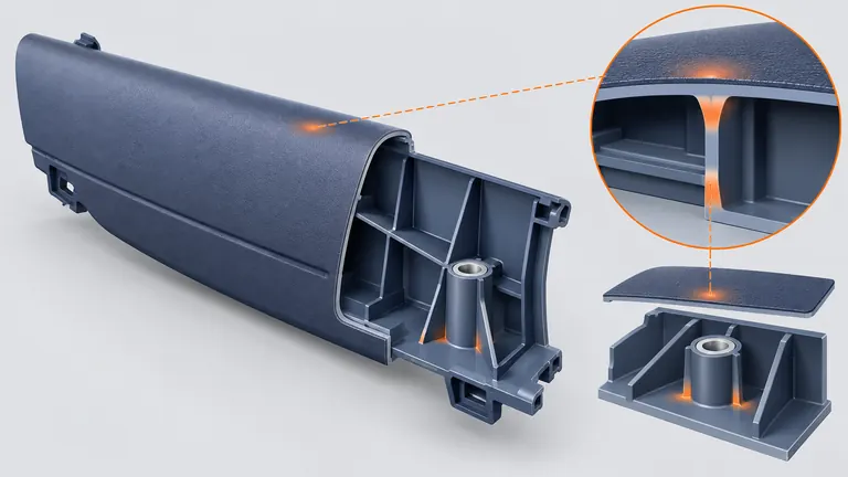
Ribs and bosses can stiffen and locate an automotive trim part, yet their extra mass and restraint can print through the show surface as sink, gloss change, read-through, or distortion. A feature that works structurally may therefore fail appearance review.
Design each rib and boss from its load, assembly, molding, and visible-surface relationship. Control local thickness, transitions, draft, support, and distance from the appearance surface; then verify the exact resin, texture, gate, cooling, process, and viewing standard. Generic ratios are starting points, not acceptance guarantees.
Begin with the feature’s job and the customer’s appearance zones
A rib should not exist merely because “plastic parts need ribs,” and a boss should not be sized from a preferred screw before the assembly load is understood. Define what each feature must do and what appearance risk it can create.
Map the part into appearance and functional zones. Identify Class A or customer-defined show surfaces, indirect viewing areas, hidden surfaces, light paths, grain direction, gloss boundaries, and regions covered by adjacent trim. Record expected viewing distance, lighting, angle, and approved boundary samples if the customer supplies them. The visible effect of a rib can change with texture, color, wall curvature, and illumination, so “back side only” does not mean invisible.
For each rib, state whether it resists bending, controls vibration, guides assembly, locates a component, protects a wall, or carries load into another feature. For each boss, define screw or insert type, tightening method, clamp load, service load, installation cycles, alignment function, and mating-part tolerance. A screw boss that also acts as a locator can over-constrain the assembly; separate functions when practical.
Create a feature map linking every rib and boss to the nearest show surface, nominal wall, gate flow path, cooling channel, ejector, and mating feature. Include load direction and accessible inspection points. This forces engineering, tooling, and appearance teams to review the same geometry.
BASF’s troubleshooting guidance identifies sink marks and gloss variations as distinct molding problems, and its engineering-thermoplastics brochure illustrates how rib geometry affects sink risk (BASF injection molding troubleshooter). These references support the mechanism, not a universal dimension. Use the chosen resin supplier’s design and processing guidance for the actual grade.
The output of this stage is not a polished CAD model. It is a list of functional loads, appearance constraints, assembly interfaces, and uncertainties that the rib/boss layout must resolve.
Control local mass and transitions instead of applying one ratio blindly
Sink and read-through arise when a thick local section cools and shrinks differently from the surrounding wall or when packing and cooling cannot compensate uniformly. Ribs, boss bases, gussets, and intersections can combine into a mass much larger than any single dimension suggests.
Start with the resin supplier’s recommended rib-thickness range relative to the adjacent wall, then check the complete cross-section. Measure the effective thickness through the rib root, fillet, wall, boss base, and crossing features. Avoid stacking a rib, boss, and attachment pad on the same show-surface location. Core out solid bosses and use separated gussets when the load path allows. Blend transitions without creating a heavy wedge.
Draft affects both ejection and root geometry. A tall rib with inadequate draft can drag, polish, or stress during ejection; too much taper can weaken its tip. The nominal ratio must identify where thickness is measured. Fillets reduce sharp stress concentrations and assist flow, but an oversized fillet can recreate the local mass that the designer intended to avoid.
| Geometry review | Evidence to request | Decision |
|---|---|---|
| Rib root and adjacent wall | Section views with dimensions and resin guidance | Accept, thin, core, or move |
| Boss base and screw engagement | Fastener requirement and load path | Separate locator, resize, or test |
| Rib/boss intersections | Local-thickness map | Stagger, interrupt, or redesign |
| Draft and ejection | Mold pull direction and ejector concept | Increase draft or change release plan |
| Show-surface relationship | Appearance-zone overlay | Move feature or plan validation |
Do not treat “50 percent of wall” or another remembered ratio as proof. Filled materials, semi-crystalline resins, thick walls, high-gloss surfaces, and aggressive textures behave differently. Gate location, packing, mold temperature, and cooling layout can amplify or reduce visible effects. A lower rib thickness may reduce sink but also reduce stiffness or make filling difficult.
Document the chosen geometry with its basis: resin grade, nominal wall, appearance classification, structural assumption, fastener, and trial criterion. That record prevents a later tooling change from being judged against an unstated rule.
Design bosses as part of the assembly and tolerance system
A boss creates a local molded feature, but its success is determined during assembly. Screw engagement, hoop stress, insertion torque, clamp load, locator strategy, mating-hole position, and access all affect whether it cracks, strips, distorts the show surface, or pulls the assembly out of alignment.
Obtain the actual fastener or insert specification and the mating-component definition. Confirm pilot diameter, engagement length, lead-in, counterbore, head clearance, installation speed and torque method, expected service removal, and environmental condition. Supplier recommendations for a specific thread-forming screw or insert are more useful than a generic boss chart. If the hardware is not frozen, design a validation plan that compares defined options rather than leaving the boss dimension open.
Support the boss in the load direction without making it a solid column to the cosmetic wall. Gussets can carry bending and torque, but their thickness and intersections must be reviewed for sink. Where the boss must locate an assembly, define which degrees of freedom it controls and which features provide clearance. Two rigid round locators can cause binding when molded position variation and mating-part tolerances accumulate; a round-and-slot strategy may better express the functional constraint.
Plan ejection and tooling access. Deep bosses need venting and sufficient core strength. Small core pins can deflect or retain heat. Ejectors should push on structurally supported regions without marking the show surface. If a boss requires a side action, insert, or replaceable core, include service access and spare strategy.
Set inspection to the function. Diameter alone may not prove assembly. Position to the functional datum, perpendicularity, engagement depth, flash, and damage after installation can matter. Use the intended datum simulation and part condition. For appearance-sensitive trim, inspect the opposite show surface before and after screw installation because clamp load can reveal read-through not visible on an unassembled part.
Assembly approval should include installation-window evidence and representative mating components. A single hand-built sample at low torque is not enough when production uses powered drivers and stacked tolerances.
Review mold filling, cooling, texture, and ejection together
Good nominal geometry can still produce a visible defect if the mold and process create uneven pressure, temperature, or release. The DFM review should therefore connect part features to the proposed gate, flow front, vents, cooling, steel construction, and ejector plan.
Gate location controls how pressure reaches the rib or boss and whether air can escape. A rib aligned with flow may fill differently from one reached after the main wall has frozen. Intersections can trap gas or create hesitation. Packing effectiveness falls after the gate freezes, so a far-end boss may show more sink even if its dimensions match a near-gate boss. The supplier should explain expected filling sequence and the trial checks that will confirm it.
Cooling near a boss core or rib cluster can be constrained by thin steel, actions, or ejectors. Ask for section views showing available cooling and heat-removal paths. A cold show surface and hot core can create differential shrinkage or delayed distortion. Do not accept a cosmetic promise based only on a nominal mold temperature; require the actual circuit concept and production-relevant trial evidence.
Texture changes release force and visible reflection. Draft that is adequate for a polished surface may be inadequate for grain. Obtain the texture supplier’s and customer’s draft requirements for the specified grain and depth. Define where grain may fade, break, or be interrupted around parting lines and actions. Protect critical surfaces from ejector, gate, and vent evidence.
Illustrative example—hypothetical, not an AutoMoldingPro project. A door-trim bezel needs a screw boss behind a low-gloss show surface. CAD review finds that two full-thickness gussets intersect the boss base directly under a highlight line. The team separates the gussets, cores the boss base, confirms fastener engagement, adds cooling access, and defines a T1 inspection under the customer viewing setup before and after screw installation. The example demonstrates a decision path, not guaranteed defect prevention.
The tooling release package should show feature sections, gate and flow rationale, venting, cooling, ejection, texture boundaries, and steel-safe correction directions.
Approve ribs and bosses through staged evidence
The acceptance plan should test function and appearance at the conditions that expose risk. Separate tool learning, dimensional confirmation, assembly validation, and final appearance approval instead of trying to close everything with one T1 sample.
At the first trial, inspect complete fill, burn, hesitation, drag, ejection, flash, sink, read-through, gloss variation, and distortion by cavity. Record resin grade, color, moisture preparation where applicable, machine, mold temperatures, fill/pack settings, cooling time, and sample age. Appearance can change as parts cool or condition; define when evaluation occurs.
Measure functional datums, boss diameter and position, engagement, rib-critical dimensions, and assembly interfaces using an agreed fixture or datum simulation. Run screw installation with production-intent hardware and equipment. Record torque or other acceptance data only when the customer or design authority defines the method and limits. Check cracking, stripping, boss whitening, clamp-induced deformation, and post-assembly show-surface change.
For appearance, use the customer’s lighting booth, viewing geometry, color/gloss method, grain reference, and boundary samples where required. Do not replace visual approval with one instrumental reading unless the specification allows it. SAE J361 is a recommended practice for visual evaluation of automotive trim color matches and highlights controlled observers and conditions (SAE J361); customer-specific standards remain controlling.
Maintain an issue log that identifies cavity, feature, condition, photograph, measurement, suspected mechanism, action, and verification. Classify corrections as steel removal, steel addition or insert replacement, process optimization, texture work, or product-design change. Confirm approval before irreversible work.
For an RFQ or DFM review, provide native CAD, controlled drawing, exact resin/color, nominal wall, appearance zones, grain specification, fasteners, mating parts, load assumptions, assembly equipment, inspection datum, and customer viewing criteria. Ask the supplier to return annotated sections and a staged acceptance plan. This makes ribs and bosses reviewable engineering features instead of hidden cosmetic risks.
Conclusion
Approve ribs and bosses only after their load path, local mass, assembly tolerance, mold conditions, and appearance criteria agree. Provide the resin, fastener, mating parts, texture, and viewing standard before tooling release, then verify both unassembled and assembled parts by cavity.