
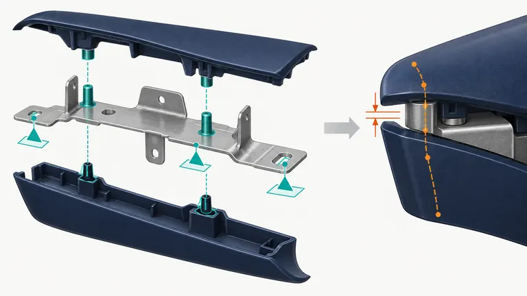
Individual plastic parts can meet their drawings while the assembled trim still shows an uneven gap, poor flushness, clip misalignment, or assembly force. The failure often lies in the chain between datums, locators, mating features, measurement, and real part behavior—not in one isolated dimension.
Build the stack from the functional assembly loop. Define datum simulation and degrees of freedom, identify contributors and assembly sequence, choose worst-case or statistical analysis deliberately, and verify the model with production-intent parts and fixtures. Tighten only contributors that materially improve the functional result.
Define the functional requirement and the assembly loop
A tolerance study should begin with the gap, flush, alignment, engagement, or force that the customer must accept. Starting from a collection of drawing tolerances can produce a precise calculation for the wrong physical relationship.
Mark the two surfaces or features that define the result and trace a closed loop through every contributor: vehicle or subassembly locating points, brackets, mating trim, clips, holes, slots, bosses, foam or seals, and the molded part. Include assembly sequence and load direction. A flexible trim part may seat differently before and after screws, clips, or adjacent components are installed.
Define the requirement over location and condition. A nominal gap may vary along a long edge; flushness may be sensitive to local curvature. State whether the part is free, fixtured, or assembled; temperature and conditioning state; fastener torque or clip engagement; and measurement locations. Avoid one headline gap value when the appearance is governed by a profile.
Classify contributors as dimensional, geometric, material/thermal, process, assembly, and measurement. Mold shrinkage, warpage, clip compliance, datum contact, fixture repeatability, and operator sequence can all influence the observed result. Decide which are controlled by drawing, process, fixture, or work instruction.
ASME Y14.5 establishes rules for dimensioning, geometric tolerancing, datum references, and product-definition interpretation (ASME Y14.5). The governing drawing must state its applicable standard and edition. A stack-up article cannot replace the design authority’s GD&T or a customer-specific gap-and-flush method.
Create a loop diagram with signed directions. Positive and negative contributors must follow one coordinate convention. Record nominal, tolerance distribution or limits, source document, and owner. This visual check often reveals omitted clips or double-counted dimensions before any calculation begins.
Build a datum strategy that reproduces how the part is located
Datums are not labels added to simplify inspection. They create the reference frame from which orientation and location are controlled and verified. If the inspection fixture locates the part differently from the assembly, measured conformance may not predict installed fit.
Identify which physical features arrest each degree of freedom in the vehicle or subassembly. The primary datum establishes the first contact relationship; secondary and tertiary locators complete the constraint according to the product definition. Flexible molded surfaces can distort when clamped, so define datum targets, contact sizes, sequence, and permitted forces. A broad nominal surface may be a poor simulator if the actual assembly contacts pads or pins.
Review locator schemes for over-constraint. Two round pins in two close-fitting round holes may bind as position and size vary; a round locator plus a slot can constrain translation while allowing thermal or manufacturing variation in one direction. Clips can locate, retain, or simply provide preload; do not assume they perform all three functions. A screw may pull a part into position but also distort a visible edge.
Tie every stack contributor to the same datum reference frame or transform it explicitly. Coordinate dimensions measured from unrelated origins cannot be added without understanding correlation and orientation. Profile tolerances can control a surface relative to datums more effectively than many independent point dimensions, but the design authority must choose the correct control and verification.
Plan inspection with the datum strategy. Document fixture contacts, clamping, part temperature, conditioning, measurement path, and gage repeatability. Compare CMM data, checking fixture results, and assembled-vehicle measurements only after confirming they simulate the same relationships. ASME’s GD&T guidance emphasizes datum reference frames and verification as part of communicating form, fit, function, and interchangeability (ASME Y14 standards).
The output should be a datum simulation specification shared by CAD, tooling, fixture, quality, and assembly teams—not merely datum letters on a drawing.
Choose and calculate the stack-up method transparently
Worst-case and statistical methods answer different planning questions. Worst-case arithmetic asks whether the requirement is met when every contributor reaches its allowed extreme in the adverse direction. Statistical methods estimate a distribution under defined assumptions about centering, variation, and independence.
For a linear worst-case stack, assign each contributor a signed sensitivity and add its adverse limit. This is conservative and useful where interchangeability must be guaranteed within stated limits, but it can drive expensive tolerances if many contributors are unlikely to align at extremes. A root-sum-square or Monte Carlo approach can be more realistic for capable, centered, stable contributors, yet it is invalid if distributions are unknown, biased, correlated, truncated by sorting, or changed by assembly force.
| Stack input | Required record | Common mistake |
|---|---|---|
| Functional response | Gap/flush location, direction, condition | Using a nominal drawing dimension only |
| Contributor | Nominal, tolerance or distribution, sensitivity | Omitting geometric or assembly variation |
| Datum simulation | Contacts, sequence, restraint | Mixing fixture and vehicle references |
| Correlation | Common tooling/process effects | Treating related points as independent |
| Method | Worst-case, RSS, or simulation assumptions | Reporting one number without confidence basis |
| Verification | Measurement and assembly plan | Tightening CAD before measuring reality |
Illustrative example—hypothetical, not an AutoMoldingPro project. A bezel-to-panel gap depends on panel-hole position, bracket position, bezel locator position, clip clearance, and local bezel profile. The team first calculates a worst-case boundary. It then uses measured distributions for a statistical model, keeping correlated cavity and fixture effects together. Sensitivity shows the bezel profile and bracket location dominate; halving an unrelated boss-diameter tolerance barely changes predicted gap. The example omits project numbers intentionally and demonstrates how to direct effort.
Show equations, units, signs, assumptions, and revision. Run sensitivity by changing one contributor at a time. Do not present a statistical result as a guarantee. Use it to choose design changes, locator changes, process controls, or additional evidence.
Manage molded-part behavior, assembly force, and correlation
Plastic trim is not a rigid coordinate cloud. Temperature, moisture, residual stress, ejection, storage, and assembly preload can change shape. A useful tolerance model must decide which behaviors belong in the nominal design, drawing limits, process distribution, or test condition.
Measure parts at a specified age and condition. Semi-crystalline or moisture-sensitive materials may continue to change after molding; large thin trim can relax or deform in packaging. Record resin grade, color package, mold cavity, process condition, cooling, conditioning, fixture time, and temperature. Do not merge data from uncontrolled states into one distribution.
Capture geometric correlation. Points on one warped edge move together; dimensions from the same cavity share steel and cooling influences. Treating every point as independent can understate tail behavior. Compare cavity-to-cavity means and within-cavity variation. A multi-cavity tool may require cavity-specific offsets or correction before pooling data.
Assembly can either absorb or amplify variation. Clips have insertion direction, free play, retention, and compliance. Foam and seals introduce compression force. Screws create pull-down and sequence effects. A locating tab may bottom before the visible edge seats. Include contact and force logic in the model, then use assembly trials to check it.
When the model misses reality, do not simply add a safety factor. Investigate datum mismatch, omitted contributor, nonlinear contact, part flexibility, measurement error, or process drift. Use digital variation simulation or finite-element methods when complexity requires them, but validate their restraints and material assumptions.
The engineering decision may be to move a locator, open clearance, change clip direction, stiffen a region, correct cooling, revise the fixture, or tighten a specific feature. Tightening every molded dimension usually adds cost without guaranteeing better appearance. Preserve a contribution budget so later changes can be assessed against the functional allocation.
Validate the stack and turn it into release controls
A calculated stack becomes useful only when sample assemblies and serial controls confirm the predicted relationships. Build verification into tooling and launch plans.
At T1 and later trials, measure the molded contributors by cavity in the defined part state, then assemble with production-intent mating parts, clips, fasteners, fixtures, and sequence. Measure the functional gap or flush at specified stations under the customer viewing or measurement method. Record component revisions and lot/cavity identities so outliers can be traced.
Compare observed mean, range, shape, and cavity effects with model assumptions. If parts are hand-selected, reworked, or forced during assembly, mark the data accordingly. Do not use a curated showcase assembly as evidence of random interchangeability. When mating components are not production intent, treat the result as learning rather than final acceptance.
Create a release checklist:
| Gate | Required evidence | Release question |
|---|---|---|
| Design | Functional loop, datum scheme, stack method | Is the requirement allocated coherently? |
| Tooling | Steel-safe features and fixture concept | Can dominant contributors be corrected and measured? |
| Trial | Cavity data and production-state condition | Does molded behavior match assumptions? |
| Assembly | Random-build gap/flush and force evidence | Does the system fit without selection or hidden rework? |
| Serial | Control plan, reaction, change triggers | Will the approved relationship remain controlled? |
Update the drawing, CAD, fixture definition, work instruction, and control plan where decisions change them. Customer-specific requirements determine formal approval or resubmission. Preserve the stack revision and measured validation set.
For an RFQ, provide assembly CAD, controlled drawings, datum and measurement methods, mating-part data, clip and fastener specifications, material/conditioning state, gap-and-flush criteria, appearance zones, and validation quantities. Ask the molding supplier to identify dominant molded contributors, fixture assumptions, cavity plan, and steel-safe corrections. This lets the supplier quote the actual assembly decision rather than isolated tolerances.
Conclusion
Build trim stack-ups from the installed functional loop and a reproducible datum strategy. Calculate assumptions openly, include plastic and assembly behavior, and verify random production-intent assemblies by cavity. Tighten the contributors that materially control gap and flush, not every dimension.