
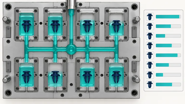
A multi-cavity mold can meet total shot weight while individual cavities fill, pack, cool, and shrink differently. Pooling the parts may hide short shots, flash, dimensions, appearance, or strength that follow a cavity pattern and later escape into serial production.
Evaluate balance by cavity through fill-only studies, weight and dimensional data, process traces, and production-length confirmation. Separate feed-system imbalance from cavity, venting, cooling, gate, and measurement effects. Approve a common process only when every active cavity has an acceptable and stable window.
Define balance in terms of the part requirements
Geometric symmetry is helpful, but the purchasing question is not whether runner lengths look equal. It is whether every cavity produces conforming parts under one controlled process with adequate margin.
Start by listing cavity-specific product risks: complete fill, flash, gate quality, weld-line location, dimensions, warpage, weight, appearance, and functional performance. Identify the features at end of fill and near the gate. A cavity that fills slightly later may still be acceptable for a forgiving part; a small delay can be critical at a thin clip, sealing edge, or cosmetic texture.
Define the mold configuration: identical or family cavities, cold or hot runner, natural or artificial balance, gate type, valve sequence, cavity identification, and any intentionally blocked or spare cavities. Confirm the machine, resin grade, color or additive, mold temperatures, and intended cavitation. Balance observed with a different resin or machine may not transfer.
Autodesk explains that runner layout affects material use and part quality, and that unbalanced cavities can create overpacking, hesitation, and pressure loss (Autodesk runner layout). Its guidance also distinguishes cavity fill from the runner changes used to make fill more simultaneous. That is a useful engineering basis, not a customer acceptance limit.
Set a balance-study plan before optimization. Define process state, sample sequence, number of repetitions, cavity marking, weighing resolution, dimensional and appearance checks, and how startup or color change is treated. Decide whether the goal is tool debugging, process establishment, capability evidence, or serial monitoring. Each stage needs different sample depth.
Do not reduce balance to one percentage without the underlying data. A summary metric can trend the system, but product acceptance must remain tied to the actual cavity-specific requirements and approved reaction plan.
Separate feed imbalance from other cavity-specific causes
Different cavity results can originate in the runner system, but also in gates, vents, cavity steel, cooling, hot-runner temperatures, valve timing, ejection, sensors, or measurement. Correcting the wrong mechanism may merely move the defect.
Use a staged investigation. First verify cavity identity and measurement repeatability. Inspect cavity and gate dimensions, vent cleanliness, shutoffs, inserts, cooling connections, hot-runner heaters and thermocouples, and valve-gate actuation. Confirm that mold setup and water circuits match the approved configuration.
Run a fill-only or short-shot study using a controlled transfer point so the flow pattern can be compared before packing masks it. Weigh cavity parts with runner segmentation where possible. Compare which cavities reach end-of-fill first, where flow fronts stop, and whether the pattern repeats. Then restore packing and compare pressure-sensitive dimensions, flash, and weight.
| Observation | Possible mechanisms | Next evidence |
|---|---|---|
| Same cavities consistently heavy | Runner/gate advantage, hot-runner temperature, valve timing | Fill sequence, gate dimensions, cavity pressure |
| Pattern changes shot to shot | Gate instability, melt variation, heater control, check ring | Time traces, temperature/current, shot repeatability |
| Equal fill but different dimensions | Cooling, steel, venting, ejection, measurement | Circuit data, cavity layout, conditioned dimensions |
| One end-of-fill defect | Local vent or wall/gate interaction | Vent inspection and controlled short shots |
| Balance changes after maintenance | Wrong insert, gate, hose, or setting restored | Configuration and setup audit |
RJG describes cavity fill time and high/low cavity traces as tools for detecting balance, blocked cavities, valve-gate, and hot-runner problems (RJG cavity fill-time overview). Use such sensor data when available, but do not assume it replaces product measurement.
The investigation should produce a cause hypothesis supported by repeated evidence. Avoid compensating for a steel or cooling difference with arbitrary heater offsets unless the engineering team understands material-temperature and maintenance consequences.
Design or correct the feed system with auditable assumptions
A naturally balanced cold-runner layout aims for equivalent flow paths; an artificial balance changes runner resistance to coordinate cavity fill. Hot-runner systems add thermal behavior and, for valve gates, timing and mechanical control. Every method has practical constraints.
For a new tool, analyze each cavity’s fill behavior and then the complete feed system using the exact geometry and representative material data. Autodesk’s runner-balance analysis varies runner dimensions to support simultaneous filling while controlling pressure and feed volume, subject to user constraints (Autodesk Runner Balance analysis). Review the model revision, mesh, gate geometry, material dataset, process limits, and constraint choices. A simulation result is a design input, not final proof.
Check manufacturability and service. Very different runner diameters can create freeze, ejection, or pressure issues. Small gates may wear or clog. Hot-runner temperature offsets can alter resin history and make startup unstable. Valve sequencing can improve fill control but adds controller, sensor, timing, and maintenance requirements. Document the approved hardware and settings.
For an existing tool, prefer reversible or measurable corrections where practical: clean and restore vents, repair worn gates, correct verified dimensions, restore water flow, or adjust defined valve timing. Runner or gate modifications affect packing, shear, vestige, and weld lines, so revalidate relevant requirements. Do not polish or enlarge a runner based on one short-shot image without checking the entire system.
Illustrative example—hypothetical, not an AutoMoldingPro project. An eight-cavity clip mold shows cavities 7 and 8 consistently light. Short shots confirm later fill, but inspection also finds lower water flow on that branch and contamination at one gate. The team cleans and verifies cooling, restores the gate to drawing, repeats the fill-only study, and then decides whether runner work is still necessary. The sequence prevents permanent steel modification from masking maintenance causes.
Record before/after geometry, settings, samples, and results. This history is essential when the mold is transferred or later repaired.
Prove a common process window across every cavity
Matching fill at one center setting does not prove that the mold has a robust common window. Early cavities may flash at the high side while late cavities short at the low side, leaving no practical overlap.
Establish the intended process with controlled resin preparation, melt temperature, mold temperature, fill profile, transfer, packing, cooling, and cycle. Conduct defined challenge points within authorized safe limits: for example, variations in fill or pack pressure, mold temperature, or material lot that represent expected production conditions. The objective is not to violate the specification but to determine whether every cavity remains acceptable under one control strategy.
Measure cavity-identified weight, critical dimensions, appearance, and functional features at each condition. Use measurement systems suitable for the tolerances and part state. Compare within-cavity variation, between-cavity means, and time trends. A pooled capability statistic can look acceptable while one cavity mean sits near a limit; report cavity-level data.
Check sustained operation. Thermal stabilization, gate wear, vent buildup, hot-runner control, and cooling can change balance after startup. Include startup, steady-state, interruption, and restart if they are material to the program. Verify the normal production cycle and automation rather than a slowed inspection run.
Define acceptance and reaction. If one cavity approaches a limit, can the process be adjusted without harming another? Which conditions trigger segregation, cavity shutdown, maintenance, or customer notification? If individual cavity control is used, identify the hardware, validated settings, failure detection, and fallback.
AIAG’s CQI-23 frames molding-system assessment around process controls and part inspection/testing (AIAG CQI-23). The customer’s control plan and approval requirements determine required studies. Balance evidence should support—not replace—those obligations.
Release only when all active cavities meet the agreed part criteria and the control/reaction plan is practical for serial production.
Preserve cavity identity and detect drift in serial production
Balance can deteriorate through gate wear, vent contamination, heater drift, water restriction, insert replacement, valve timing, or incorrect setup. Serial control needs enough cavity identity to detect the pattern before pooled inspection hides it.
Mark parts by cavity where geometry and customer requirements allow, and maintain a mapping between cavity number, physical mold position, hot-runner zone, cooling circuit, insert, and measurement data. Verify markings remain legible and do not create a functional or appearance issue. For parts that cannot carry visible identification, define an alternative traceability method during validation and containment.
Trend a small set of sensitive measures: cavity weight, critical dimension, fill or cavity-pressure timing, gate appearance, flash, short-shot occurrence, and relevant temperature or flow indicators. Select measures that respond to known risks. Establish control and reaction criteria from approved data, not arbitrary percentages.
After mold maintenance, gate replacement, hot-runner repair, cooling cleaning, insert change, material change, or press transfer, run a risk-based balance confirmation before normal release. Compare to the approved cavity fingerprint. Preserve the previous and new condition in the mold history.
For an RFQ, provide part revisions, resin, annual demand, required cavity count, machine range, critical features, cavity-identification rules, expected validation, and customer submission requirements. Ask the supplier for runner concept, balance analysis assumptions, cavity study plan, correction strategy, process-window evidence, and serial monitoring plan.
Link this analysis to the earlier decision on single-, multi-cavity, or family molds and to run-at-rate capacity validation. Cavity balance proves equal and acceptable molding behavior; it does not by itself prove required capacity.
Conclusion
Treat runner balance as a cavity-specific product and process decision. Diagnose feed, gate, vent, cooling, steel, and control causes separately; then verify a common process window and sustained operation. Preserve cavity identity so serial drift can be detected and corrected.