
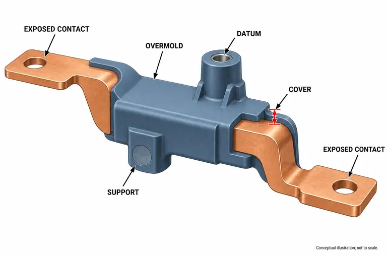
In an insert-molded busbar, the plastic is not simply a protective coating. It locates conductors, separates exposed and covered zones, supports terminals, reacts to molding pressure and shrinkage, and interfaces with the final electrical assembly. Ambiguous envelope data can produce metal shift, thin cover, flash on contact areas, or hidden voids.
Release the insert and plastic as one controlled interface. Define metal datums, exposed and overmolded regions, minimum and nominal cover, allowable parting and gate areas, conductor position after molding, material and cleanliness, tooling support, and the validation owned by the component and system teams. Do not infer electrical-system compliance from molding inspection alone.
Define the functional zones before designing the plastic
Mark every conductor surface by purpose: electrical contact, weld or bolt interface, sealing interface, overmold bond area, tooling location, inspection datum, keep-out, and permissible witness area. A colored 3D model plus a controlled 2D section map is usually clearer than notes such as “overmold as shown.”
Specify which metal geometry is controlled before molding and which plastic geometry is controlled afterward. The stamped insert may have its own profile, flatness, bend, edge condition, plating, and burr direction. Those variations consume the plastic-envelope tolerance. Define the datum transfer from loose insert to molded component so inspectors do not align the metal one way and the plastic another.
Identify exposed zones with limits for flash, resin smear, scratches, oxidation, and handling marks. Define whether masking, shutoff steel, or post-mold cleaning is allowed. A contact surface that is visually clear can still be dimensionally obstructed; use functional gauges or mating components where appropriate.
For covered regions, state nominal wall and the minimum allowed after combining insert tolerance, loading error, tool deflection, and molding movement. Avoid presenting a generic wall value as an insulation guarantee. Creepage, clearance, dielectric strength, tracking, thermal rise, vibration, and environmental requirements belong to the electrical system design and its applicable standards.
Provide sections through bends, branches, terminal transitions, weld tabs, bosses, and conductor crossovers. These are common locations for local thinness, resin hesitation, air traps, stress concentration, and difficult steel shutoffs.
Control the loose insert and its position under molding pressure
The insert must arrive in a repeatable state and remain located while melt fills the cavity. Inspect material, thickness, plating or surface treatment, stamped profile, bend angles, burr, cleanliness, and critical datums. Define packaging that prevents distortion and contact damage.
Tooling locators should constrain required degrees of freedom without over-constraining a variable stamping. Use support points near areas exposed to melt force, but keep them away from forbidden witness or electrical zones. Review how the insert is loaded, detected, clamped, and released. Poka-yoke orientation and sensors may be needed to prevent missing, doubled, reversed, or wrong-variant inserts.
Eaton describes unsupported busbars being affected by the melt front and uses cavity-centering technology to constrain conductor position during insert molding (Eaton insert molding). This observable mechanism is broadly relevant, although Eaton’s proprietary solution and performance claims should not be generalized to another tool.
Use fill analysis as a design aid to assess first contact, pressure imbalance, hesitation, weld locations, and air traps, then verify with trials. Gate location can push or twist the insert; symmetric-looking flow does not guarantee balanced force. Venting and overflow strategy must avoid contaminating exposed contacts. Ejection must support the composite part without bending terminals.
Track insert lot and molded batch. If metal position differs by cavity, preserve cavity identity. Inspect position with datums representing assembly, not only free-state best fit. Where hidden displacement matters, sectioning, CT, electrical tests, or designed witness features may be justified by risk.
Design the metal–plastic interface for manufacturing and service conditions
Metal and polymer respond differently to temperature and load. Plastic shrinkage can bow a thin conductor or create residual stress; the conductor can restrain the molding and cause warpage or cracking. Sharp metal edges and abrupt plastic thickness transitions concentrate stress.
Review edge radii, holes, slots, tabs, knurls, and mechanical retention features. Retention geometry may help resist pullout or rotation, but it can also create weld lines, trapped gas, or thin steel conditions. Do not assume chemical adhesion unless the exact metal surface, resin, preparation, and aging are validated. Many designs rely primarily on mechanical interlock and controlled encapsulation.
Separate sealing from retention. If the overmold must resist fluid ingress, define the leak path, pressure differential, interfaces, and test conditions. A visually complete overmold is not proof of a seal. Likewise, an electrical withstand test cannot by itself prove long-term mechanical retention.
| Interface question | Drawing/RFQ input | Evidence before release |
|---|---|---|
| Where must metal remain exposed? | Zone map and flash/contamination limits | Visual, dimensional and functional contact check |
| Where is plastic cover critical? | Controlled sections and minimum-cover requirement | Section/CT or qualified measurement approach |
| How is the insert located? | Metal datums and support/witness permissions | Loading study and position capability |
| How is retention achieved? | Interlock geometry and load direction | Pull, push, torque or assembly test |
| Is sealing required? | Leak path, medium, pressure and conditioning | Defined leak test after applicable aging |
| What is electrical responsibility? | System requirements and test owner | Component and system validation plan |
Choose the exact resin from thermal, mechanical, electrical, chemical, molding, and declaration requirements. Use producer data under applicable conditions, then validate the molded component. Color is not evidence of voltage class or flame performance.
Validate the composite part without overstating compliance
The validation plan should connect incoming insert quality, molding process, geometry, environmental exposure, mechanical tests, and electrical-system tests. Assign each requirement to the organization with the design authority and suitable equipment.
At molding trials, document insert lot, cavity, resin lot and conditioning, machine, process window, load method, sensors, reject logic, and sample timing. Check fill, flash, short shots, burns, insert movement, plastic cover, exposed zones, warpage, terminal position, and ejection damage. Challenge low and high process-window conditions where risk justifies it.
Measure conductor and plastic datums after molding and after specified conditioning. Validate mating, torque, weld access, connector position, and retention. Electrical testing may include resistance, dielectric withstand, insulation resistance, temperature rise, or other program-defined tests, but the article cannot prescribe acceptance values without the system specification.
Illustrative example—hypothetical, not an AutoMoldingPro project. A bent copper busbar has two bolted contact pads that must remain resin-free and one overmolded branch. The team defines pad keep-outs, metal datums, support-pin witnesses, minimum plastic-cover sections, and post-mold terminal position. Trial samples show movement near the branch when filled from one side, so gate and support strategy are revised before system electrical testing. No compliance claim follows from the molding result alone.
After aging, recheck cracks, delamination where relevant, retention, dimensions, sealing and electrical functions specified by the customer. Preserve destructive sections and test conditions. A passing initial sample cannot substitute for production controls and change management.
Use a busbar RFQ package that closes interface ambiguity
Provide separate and assembled CAD, released 2D drawings, material and plating specifications, burr direction, insert supply condition, exposed/covered zone model, critical sections, datums, mating components, annual demand, cavitation assumptions, packaging, cleanliness, traceability, and validation requirements.
Ask the supplier to return a DFM package covering insert tolerance, loading automation, orientation prevention, supports and witnesses, gate/flow force, shutoffs, venting, minimum-cover measurement, ejection, cavity identification, sensor strategy, scrap handling, and change control. Require a clear division of responsibility for stamping, plating, insert supply, molding, electrical testing, and final assembly.
Do not request a quote from a cosmetic rendering alone. The supplier cannot price reliable tooling or inspection without sections, tolerances, contact keep-outs, test scope, and production rate. Where the customer has not completed electrical design, label unknowns and keep the quotation conditional.
To request a molding feasibility review, submit the conductor and overmold models, zone map, exact materials, terminal interfaces, volume, process ownership, and validation matrix through the AutoMoldingPro contact page. The outcome should be an interface and evidence review, not a promise of system certification.
Include packaging and handling in that scope. Exposed terminals can be bent, scratched, contaminated, or forced out of position after molding even when the part left the press correctly. Define protective trays or separators, stacking limits, contact protection, cleanliness, orientation, label traceability, and inspection after transport. If the component will be welded, bolted, or sealed later, confirm that packaging residues and protective materials do not interfere. Transport trials should use the intended pack quantity and route where required, and any damage must be distinguished from molding defects before process changes are made.
Conclusion
An insert-molded busbar succeeds when metal identity, location, exposed zones, plastic cover, tooling supports, and validation ownership are controlled together. Release sections and datums, challenge insert movement in trials, verify the composite part, and reserve electrical compliance decisions for the applicable component and system requirements.