
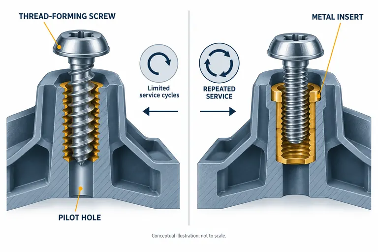
A joint can pass an initial assembly and still crack, strip, loosen, or lose clamp after temperature, vibration, service removal, and polymer creep. Choosing a thread-forming screw or metal insert by unit price alone ignores the boss, resin, driver, load path, and required service life.
Use a thread-forming screw when the thermoplastic boss, installation window, clamp requirement, and limited service cycles can be validated together. Use a metal insert when repeat disassembly, higher or more stable clamp load, metal-thread compatibility, or repair strategy justifies the added part and process. Neither option is universally superior.
Translate the assembly duty into measurable joint requirements
Begin with what the joint must do. Define clamp load, separating and shear loads, vibration, temperature and fluids, expected assembly count, service removals, installation direction, package space, grounding or conductivity needs, and consequence of failure. “M4 screw required” is an output, not a complete requirement.
Identify the plastic by exact grade, reinforcement, moisture/conditioning state, and molding process. Polymer stiffness, ductility, creep, fiber content, weld lines, knit lines, and local orientation affect the boss. A geometry proven in unfilled PP cannot be copied to a glass-filled polyamide without testing.
Map the load path. Is the screw only locating a light cover, clamping a gasket, retaining an electrical connector, or carrying structural loads? Does the joint bottom on a rigid compression limiter, or does tightening compress plastic? Can the user access the screw straight, and can the driver control speed, depth, and torque? Will heat from installation or insert installation affect nearby appearance or dimensions?
Define acceptance metrics: installation torque distribution, stripping torque margin, achieved clamp load where needed, boss cracking, pullout, pushout, insert rotation, loosening, residual torque, leak or functional performance, and repeated assembly cycles. Add environmental conditioning before or during testing according to the application.
The RFQ should specify the screw system and joint, not only the fastener catalog number. Include mating component, washer or limiter, engagement depth, boss section, draft, molded pilot hole, access, driver, and process controls.
Evaluate thread-forming screws as a molded-boss system
A screw designed for thermoplastic displaces material to form a mating thread. It can reduce purchased parts and secondary operations, but the resulting radial stress and torque window depend on the complete joint.
PENCOM’s technical bulletin notes that installation torque is affected by pilot-hole diameter and draft, engaged threads, boss wall, screw finish, rpm, thread form, plastic temperature, material, and desired clamp load. It explicitly states that one published calculation cannot determine the correct installation torque for all combinations (PENCOM thread-forming screws for plastic). Use supplier guidance as a starting range, then validate actual molded bosses.
Control the pilot hole at the condition in which assembly occurs. Core-pin wear, shrinkage, moisture conditioning, fiber orientation, and cavity variation can shift diameter and roundness. Provide lead-in and sufficient boss support without creating a thick mass that sinks or warps an appearance surface. Review weld-line location around the boss and the effect of ejector or core geometry.
Develop the driver window from data. Measure drive torque, seating torque, stripping torque, depth, speed, and failures across cavities, material lots, environmental states, and tool age. Set production limits with enough separation to seat the joint without stripping or cracking. A single mean value hides overlap between weak and high-torque tails.
Thread-forming screws are attractive for one-time or limited assembly where the joint load and creep are manageable. Repeated removal can damage formed threads or generate debris. If service cycles are required, test the specified number with production fasteners and realistic alignment. Do not assume every screw can reuse the same plastic thread indefinitely.
Thread-cutting screws are a separate option for less ductile substrates because they remove material; chip control and stress behavior differ. Keep that distinction explicit during supplier comparison.
Evaluate metal inserts by installation method and failure mode
An insert provides an internal machine thread and spreads load through its external interface with plastic. It can support repeated service and a stable mating screw, but it adds an insert, installation process, inspection, and new failure modes.
Choose among heat-installed, ultrasonic, press-in, self-tapping, or mold-in inserts only after reviewing the resin, boss, volume, access, cleanliness, thermal sensitivity, automation, and load. Use the insert manufacturer’s design data for the exact series and plastic as a starting point. SPIROL’s design guide, for example, distinguishes performance mechanisms and installation options rather than presenting all inserts as equivalent (SPIROL inserts for plastics design guide).
For post-mold installation, control hole size and condition, insert orientation, temperature or energy, depth, cycle, and cooling before loading. Excess heat can soften or distort the boss; insufficient heat or energy can damage plastic or reduce anchorage. Press-in methods can create high stress in brittle or reinforced materials. Inspect depth, tilt, surrounding cracks, pushout/pullout, rotation, and thread condition.
Mold-in inserts remove a later installation step but require robust loading, location, retention, contamination control, and mold protection. Resin pressure can shift an unsupported insert. Metal temperature and surface condition can affect bonding and local flow. Sensors, poka-yoke, and post-mold presence/location checks may be needed. The tool must protect threads and allow safe ejection.
An insert does not eliminate plastic creep around the joint. If clamp force passes through plastic without a limiter, the plastic can relax even though the machine thread remains intact. Define the compression stack and use a sleeve or hard stop when required by the design.
Compare total joint risk, cost, and serviceability
Use a decision matrix with weighted program requirements rather than a universal score.
| Decision factor | Thread-forming screw | Metal insert plus machine screw |
|---|---|---|
| Purchased components | One fastener | Insert plus fastener, sometimes limiter |
| Secondary process | Direct assembly | Insert loading/installation or insert molding |
| Repeated service | Must be proven; plastic thread can degrade | Often stronger candidate, still requires cycle validation |
| Clamp stability | Sensitive to plastic and stack | Better metal thread, but plastic compression can still creep |
| Boss/process risk | Pilot hole, radial stress, strip window | Installation heat/force, pullout, rotation, position |
| Repair | Oversize or redesign may be limited | Insert may be replaceable only if boss remains sound |
| Automation | Driver control and screw presence | Additional insert feed, presence and installation controls |
| Cost | Lower part count, validation still required | Higher component/process cost; may reduce service risk |
Illustrative example—hypothetical, not an AutoMoldingPro project. A non-serviceable trim cover uses four screws and carries little sustained load. A thread-forming design is trialed across cavities and temperature states; torque distributions and appearance remain acceptable. A nearby electronic service cover must be removed several times and compress a seal. That joint uses inserts and a controlled compression stop, then undergoes repeated assembly and leak testing. The example shows requirement-based selection, not a rule for all trim and electronics.
Include quality escape risk in cost. An insert requires incoming control, presence detection, depth and thread checks, and prevention of double-loading or missing inserts. A thread-forming joint requires molded-hole and driver controls. Compare tooling, equipment, cycle, labor, maintenance, scrap, fasteners, inspection, service warranty, and change cost.
Prototype with production-intent resin and molded bosses. Machined or printed samples may have different anisotropy, holes, and residual stress. Confirm the final choice after tool trials and environmental/functional validation.
Define the validation and supplier evidence package
Create a joint test plan with sample rationale, lots, cavities, fastener lots, assembly equipment, environmental conditioning, and failure criteria. Record torque-angle or torque-depth curves when useful, not only final torque.
Test installation window and misuse conditions relevant to production: low and high pilot-hole limits, driver speed, depth, angular misalignment, repeated cycles, and material condition. After environmental exposure, check crack formation, clamp retention, loosening, pullout or pushout, insert rotation, and product function. Separate destructive development testing from production checks.
Ask suppliers for fastener/insert drawing and material, plating and compatibility, design guide, installation equipment requirements, recommended starting geometry, lot traceability, change notification, and test method. Request a sectioned-joint review during development when internal engagement is uncertain.
The release package should include joint requirements, selected components, boss drawing, tolerance analysis, process settings and limits, measurement system, trial data, environmental results, failure analysis, control plan, PFMEA links where applicable, and approved work instructions. Customer-specific submission requirements govern whether these become part of PPAP or another approval.
For a molding feasibility review, provide 3D and 2D data, exact resin, mating stack, screw or insert candidate, load and service cycles, environment, annual volume, assembly equipment, and validation requirements. Contact AutoMoldingPro with the complete joint definition so the boss, moldability, insert handling, and inspection route can be reviewed together.
Conclusion
Choose between thread-forming screws and metal inserts from the joint’s load, service, material, boss, assembly process, and validation needs. A screw saves components only when its torque window and plastic thread remain robust. An insert adds cost and controls but can better support repeat service and a defined metal thread.