
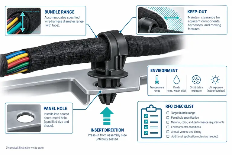
A cable-routing clip can be inexpensive yet program-critical. If the RFQ contains only a photo and nominal cable diameter, suppliers must guess the panel interface, installation direction, retention duty, environment, variants, and test scope. Quotes then describe different products.
Send an interface-led RFQ: harness bundle definition, attachment panel or stud, available installation envelope, routing direction, allowable movement, service environment, material restrictions, annual and order demand, assembly method, marking, packaging, and required validation. Separate design assumptions from customer requirements so every quotation carries the same boundary.
Describe the harness and routing duty, not just a nominal diameter
Define whether the clip holds one wire, a sleeved bundle, corrugated conduit, braided protection, connector lead, or branching harness. Provide minimum, nominal, and maximum bundle condition, including tolerance, ovality, tape overlap, splice bulges, and expected compression. A round CAD cylinder rarely represents a real harness.
State the clip’s routing function. Is it a locator that fixes position, a support that permits axial slide, a strain-relief feature near a connector, or a separator between branches? Show required cable direction, bend, free length, keep-out zones, neighboring hot or moving components, and allowable rattle or rotation. Include the mating harness model or representative samples where possible.
Specify installation and service sequence. The worker may first attach the clip to the harness and then to the vehicle, or install the body before closing a hinged strap. Access, hand force, gloves, tooling, line takt, visual confirmation, and risk of incorrect orientation affect the design. Define whether the clip is one-time use, service-removable, or expected to survive several cycles.
Provide a drawing with datums tied to vehicle assembly. Critical dimensions may include cable centerline, offset from panel, orientation, connector distance, and swing envelope. Do not tighten every plastic dimension; specify the functional location and let DFM allocate reasonable manufacturing tolerances.
If multiple harness variants share the location, list each bundle and connector condition. Ask whether one flexible design can cover them without excessive looseness, or whether keyed variants are safer. Include color and marking rules only when they serve line identification or traceability.
Fully define the vehicle-side attachment interface
The panel hole, edge, weld stud, threaded stud, bracket, or mating plastic feature determines the clip’s retention mechanism. Supply 3D and 2D data for the actual interface plus tolerances, coatings, stack thickness, access from both sides, and insertion direction.
For a push-in panel clip, define hole shape and size, sheet or stack thickness range, burr direction, paint/coating condition, curvature, and backside clearance. For a stud clip, define stud diameter, thread or weld geometry, length, coating, and obstruction. For an edge clip, include flange thickness, radius, angle, and neighboring seals.
SAE USCAR44-2 covers performance testing of automotive wire-harness retainer clips and notes that application variation includes temperature, fluids, water exposure, and panel thickness. Its published scope focuses on certain designs and sheet/rolled-metal thicknesses from 0.6 to 8 mm; outside its evaluated range requires a custom test. It also cautions that conformance cannot be claimed unless all applicable requirements are verified and documented (SAE USCAR44-2).
Referencing USCAR44-2 in an RFQ is therefore not enough. Identify the applicable design type and test options, expected service condition, customer-specific amendments, sample preparation, and documentation. If the interface or duty falls outside scope, define a program-specific validation plan.
Request insertion and extraction force targets only from the controlled requirement. High retention is not automatically better: excessive installation force can damage coatings, deform panels, slow assembly, or make service impossible. Define both directions and the conditioning sequence.
Specify environment, material boundaries, and evidence
List actual temperature zones, heat sources, fluids, water or spray, humidity, salt or road debris where applicable, vibration, UV exposure if external, and required life or test sequence. Avoid broad labels such as “underhood grade” without conditions.
Material selection must consider stiffness, toughness, creep, chemical exposure, moisture response, flammability if required, color, molding, and declaration obligations. Do not name only “nylon.” Specify the released material standard or allow proposed exact grades subject to approval. A material data sheet supports screening; molded-clip retention and durability require part testing.
Define forbidden substances and IMDS responsibilities through current customer requirements. State whether the supplier submits component data, who provides harness and panel materials, and when acceptance is needed. A material declaration is not a mechanical test report.
| RFQ block | Required inputs | Supplier return |
|---|---|---|
| Harness | Bundle range, protection, direction, variants | Grip concept and accommodated range |
| Vehicle interface | Hole/stud/edge CAD, tolerance, coating, stack | Attachment concept and tolerance review |
| Packaging envelope | Keep-outs, access, assembly sequence | DFM model and installation method |
| Environment | Temperature, fluids, water, vibration, service | Exact material proposal and test matrix |
| Performance | Insert/remove, harness retention, movement, cycles | Test methods, samples and acceptance evidence |
| Production | Annual/order demand, line rate, packaging | Tool/cavity plan, process and inspection controls |
Ask for assumptions and exclusions beside the quoted scope. If the supplier assumes a standard panel thickness or room-temperature pull test, the quotation must not look equivalent to one including the full environmental sequence.
Define verification from drawing through production
Separate dimensional, installation, mechanical, environmental, and assembly validation. The DVP&R or equivalent plan should identify requirement source, sample quantity, cavities and lots, conditioning, equipment, sequence, acceptance, and report owner.
Verify clip geometry and molded condition first. Check flash, short shot, gate witness, hinge or latch, cavity identification, and dimensions tied to the interface. Then test on production-representative panels, studs, harnesses, coatings, and assembly access. Laboratory fixtures should simulate the real constraints rather than grip the clip in a way the vehicle never does.
Measure installation force, attachment retention, harness retention, rotation or sliding as specified, removal or service cycles, and performance after environmental conditioning. Review failure mode: panel damage, branch collapse, clip fracture, creep, hinge whitening, latch opening, cable abrasion, or pullout. The same peak force can hide different and unacceptable failures.
Illustrative example—hypothetical, not an AutoMoldingPro project. One clip must hold two taped bundle variants to a painted panel. The RFQ includes the full bundle range, panel-hole tolerance, coating stack, insertion direction, cable centerline, and hot-fluid exposure. The supplier proposes one flexible strap but flags that its smallest bundle may rotate. The customer either accepts controlled rotation, adds a second locator, or separates variants before tooling. The example shows how an RFQ exposes a decision.
At production release, connect resin lot, mold and cavity, process revision, inspection, test samples, pack labels, and shipment. Define reaction rules for a failed retention check. Capability evidence should address the characteristics that control assembly, not only easy-to-measure overall dimensions.
Compare quotations on a common scope
Normalize each quote using a scope matrix. Compare design ownership, included DFM, mold material and cavitation, interchangeable inserts, trials, dimensional layouts, environmental testing, fixtures, harness/panel samples, IMDS, PPAP level, packaging, spares, maintenance, and change cost.
Record every supplier assumption. One quote may include a catalog attachment adapted to the bundle; another may include a completely custom clip and validation. Tool price and piece price cannot be compared until deliverables and approval boundaries match.
Ask for a development sequence: input freeze, concept review, prototype method and its limitations, DFM release, tool build, T1, design verification, process validation, submission, and launch controls. Identify which changes after each gate affect price and timing. Do not promise a fixed lead time until customer inputs and test scope are stable.
Submit the following to AutoMoldingPro for review: clip and mating CAD, bundle range and samples, panel or stud specification, keep-outs, assembly sequence, exact environmental and test requirements, material/declaration constraints, annual volume, order size, packaging, and approval timing. The contact page can start that exchange without requiring an upload plugin; sensitive files can follow through an agreed channel.
Also define clear ownership of all mating samples and fixtures. Production-representative harnesses and coated panels may arrive later than the mold, so the schedule should state who supplies them, how many are needed, and what substitute fixtures may be used during early trials. Any substitute needs stated limitations and a later correlation check. Record whether samples can be reused after destructive pull or environmental exposure. This small planning step prevents a supplier from presenting room-temperature tests on ideal steel coupons as final vehicle-interface validation.
Conclusion
A useful cable-clip RFQ directly defines the harness, vehicle attachment, installation envelope, environment, performance, variants, validation, volume, and evidence ownership. Provide real interface tolerances and test conditions, compare quotes on the same scope, and leave no “standard automotive” assumptions hidden in the price.