
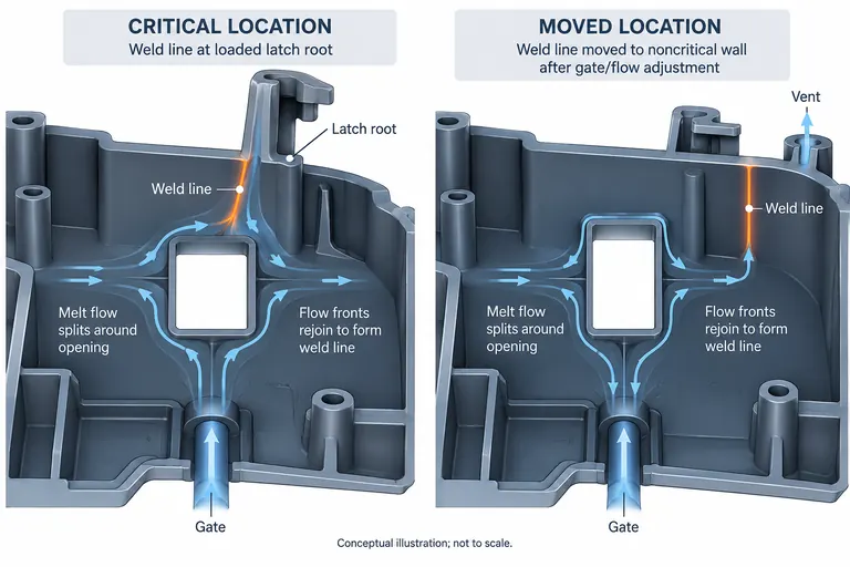
Weld lines are often unavoidable where melt flows around holes, inserts, ribs, or from multiple gates. The real engineering question is not whether a line exists, but where it forms, what function it can affect, how stable it is, and what evidence makes it acceptable.
Classify each predicted or observed weld line by appearance, structural, sealing, fastening, and electrical risk. Use geometry, gate, venting, material, and process decisions to move or improve it, then validate on production-intent parts across cavities and a defined process window. A simulation image alone cannot approve performance.
Map where flow fronts meet and what the location can damage
Mark holes, inserts, thickness transitions, flow leaders/restrictors, multiple gates, and end-of-fill regions on the part. Use fill analysis to predict meeting locations and air traps, but compare those predictions with short shots and molded samples. Mesh, material data, gate modeling, and process assumptions affect the result.
Autodesk describes weld and meld lines as regions where flow paths meet and notes that holes, inserts, multiple gates, and variable thickness can create them. Its troubleshooting guidance recommends moving lines through gate or thickness changes and improving conditions through temperature, speed, runner, packing, or venting changes, while warning that one remedy can create another molding problem (Autodesk weld-line troubleshooting).
Overlay function. A faint line on a hidden flange may be acceptable; the same line through a snap root, screw boss, seal land, pressure boundary, painted Class A zone, or high-voltage insulation path may not be. Record load direction, assembly strain, visibility, texture, coating, leak path, and environmental exposure.
Use a weld-line register with feature, predicted and actual location, cavity, appearance zone, functional risks, validation method, current status, and approved boundary. Distinguish a meld line where fronts meet obliquely from a more direct weld line, but do not assign strength from meeting angle alone.
Part drawings should define critical zones and acceptance where known. Avoid a blanket note such as “no weld lines” on geometry that necessarily divides flow. It is more useful to prohibit lines in named zones and require validation elsewhere.
Change location before trying to hide the symptom with process
Gate position and sequence strongly influence meeting location. Moving a gate can shift a line away from a critical boss or show surface, but may increase pressure, vestige visibility, orientation, warpage, or runner complexity. A valve-gate sequence can control fronts but adds hot-runner and timing controls.
Geometry changes can alter fill balance. Local thickness, flow leaders, restrictors, hole shape, rib transition, and insert position may move the meeting point. Keep changes manufacturable and assess their effect on sink, cooling, stiffness, ejection, and tolerance. Do not add mass solely to erase a cosmetic line.
Venting is essential where converging fronts trap gas. Review parting-line vents, inserts, ejectors, porous or vacuum options only through appropriate tool design. A burn mark or weak line can reflect trapped air; raising speed without correcting venting may worsen it.
Material selection affects viscosity, fillers, color, additives, and surface response. Compare exact grade data and trial behavior. Fiber-filled polymers can have orientation and local strength effects near a weld. Color or metallic pigments can make flow patterns more visible. A material substitution therefore reopens weld-line risk even when nominal polymer family is unchanged.
| Lever | Potential benefit | Tradeoff to verify |
|---|---|---|
| Gate location/sequence | Moves meeting point, changes angle | Vestige, pressure, balance, hot-runner control |
| Local wall/flow feature | Redirects fill | Sink, cooling, stiffness, dimensions |
| Venting | Releases trapped gas | Flash, maintenance, contamination |
| Melt/mold temperature | Improves front fusion | Degradation, cycle, dimensions, gloss |
| Injection speed/packing | Changes front temperature and pressure | Shear, burn, flash, warpage |
| Material grade | Different flow and interface behavior | Approval, shrinkage, performance, declaration |
Use simulation and DOE-style trials to choose a robust combination, not a cosmetic machine adjustment that only works at one favorable setting.
Validate appearance and function separately
Appearance acceptance needs controlled lighting, viewing distance and angle, surface zone, texture, color, gloss, and boundary samples. A line can change visibility after painting, plating, heat aging, or cleaning. Preserve sample revision, resin/color lot, cavity, process, and condition.
Functional validation must represent the affected duty. For a clip root, test retention or durability in the actual load direction. For a boss, test assembly and joint performance. For a seal, use defined leak conditions. For a structural region, use component tests or justified coupons that represent the molded geometry, flow, conditioning, and environment. Generic resin tensile data cannot establish local weld performance.
Compare cavities because runner balance and venting can shift line quality. Include multiple material lots and process-window conditions where risk justifies them. Record melt and mold temperature using appropriate methods, fill and pressure behavior, and actual line location. Do not report only the best sample.
Illustrative example—hypothetical, not an AutoMoldingPro project. Flow around a rectangular connector opening creates a line near a latch root. Analysis and short shots confirm the location. A gate adjustment moves the line to a non-loaded wall, while added venting removes a burn. The team then checks every cavity, latch cycling after conditioning, dimensions, and appearance boundary samples. The example demonstrates evidence flow, not a guaranteed fix.
Define acceptance before trials: allowed zone, visual boundary, load or leak criteria, conditioning, sample quantities, process limits, and approval authority. If the line remains variable or crosses a critical feature, escalate design or tooling changes rather than relaxing the criterion informally.
Control weld-line stability in production
After release, preserve the material, gate, vent, hot-runner sequence, process window, cavity configuration, and inspection method that generated accepted parts. Weld-line location and quality can change with lot viscosity, moisture, colorant, vent contamination, gate wear, heater drift, or a blocked cavity.
Include relevant characteristics and process variables in the control plan. Visual checks need current boundary samples; functional checks need defined frequency and reaction. Use process trends as diagnostic support, not a substitute for product evidence.
Maintain gates and vents against measured baselines. Record cleaning or repair and verify first-off parts from every active cavity. A polished surface or enlarged gate is a process change if it alters flow or appearance. Route material, tool, and parameter-window changes through approval requirements.
The reaction plan should stop or hold product when the line moves into a prohibited zone, exceeds the appearance boundary, burns, cracks, or fails function. Contain back to the last known conforming check by batch and cavity, verify measurement, investigate material/tool/process, correct, and obtain release evidence.
Autodesk also notes that a coarse model may not show every line and recommends using fill-time information and refined analysis when actual lines are missing from results (Autodesk support on unpredicted weld lines). Production observation remains essential.
Put weld-line decisions into the RFQ and DFM release
Provide CAD and drawing, exact material and color, cosmetic zones, texture/coating, loads, seal or electrical duties, critical keep-out zones, mating parts, annual volume, mold concept, required analysis, test methods, and customer submission rules.
Ask the supplier for predicted flow and weld locations, assumptions, vent strategy, gate alternatives, cavity risks, appearance and functional validation plan, process-window study, tool-maintenance controls, and unresolved decisions. Require screenshots or plots to identify inputs and revision, not decorative simulation images.
At DFM release, create an issue table: line ID, cause, predicted location, risk, proposed action, tradeoffs, evidence, owner, and closure gate. Keep open items visible through T1 and production approval. Link related decisions on gate location and gate vestige rather than duplicating that full analysis.
For an evaluation, send AutoMoldingPro the geometry, exact resin, critical zones, expected functions, appearance standard, volumes, and validation requirements. The proper deliverable is a risk-and-evidence plan; no supplier should promise an invisible or structurally harmless weld line without production-intent proof.
When comparing proposals, ask each supplier to separate prevention, prediction, and verification. Prevention covers gate, wall, vent, and insert choices. Prediction covers model inputs and uncertainty. Verification covers molded evidence and acceptance. A quotation that promises only “Moldflow optimization” does not reveal whether the supplier will modify the tool, repeat trials, test the affected function, or document an unavoidable line. Price these responsibilities explicitly, including additional inserts, valve-gate control, surface trials, fixtures, destructive tests, and customer resubmission. This makes the weld-line decision reviewable instead of leaving it as a late cosmetic dispute.
Conclusion
Manage weld lines by linking flow-front location to real product risk, changing geometry or gating before relying on narrow process settings, and validating appearance and function separately. Preserve the approved flow, vent, material, cavity, and process state in production, with clear reaction rules when the line changes.