
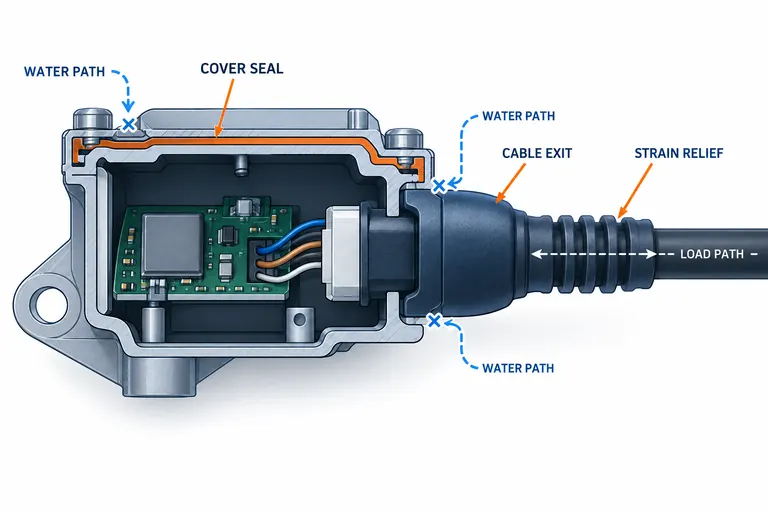
A sensor housing can have an apparently robust perimeter seal and still leak or fail at the cable exit. The same region must often stop water, retain the cable or overmold, manage bending and pull loads, protect terminations, tolerate thermal expansion, and remain moldable. Treating it as a cosmetic boot leaves critical interfaces undefined.
Design the housing joint, cable exit, seal path, and mechanical load path together. Specify mating materials and tolerances, prevent cable loads from reaching electrical joints, and validate the complete assembled sensor through the customer’s environmental and functional sequence. Do not promise an IP level from geometry alone.
Draw a complete interface and leakage-path map
Identify every boundary from the environment to the electronics: cover-to-base joint, molded housing wall, insert or terminal interface, cable jacket to overmold, overmold to rigid housing, individual wire seals, potting, vents, and fasteners. Mark which feature is the primary barrier, which is secondary, and where drainage or pressure equalization is intended.
For each boundary, record material pair, geometry, tolerance, surface condition, compression or bond mechanism, assembly method, and expected movement. Thermal expansion differences can open a joint or stress a bond. A cable can pump at an interface during vibration. Capillary gaps, weld lines, parting-line mismatch, flash, contamination, and scratches can create paths invisible in nominal CAD.
The cable exit also needs a mechanical map. Trace pull, push, twist, bend, and harness reaction loads from cable jacket through the strain relief and housing attachment. Electrical termination should not be the structural anchor. TE’s sealed connector backshell explanation separates the primary connector seal, wire sealing, backshell engagement, and strain relief, showing why a sealed path is a system rather than one feature (TE Connectivity HDSCS backshells).
State the actual environmental requirement and governing customer method. ISO 20653 or another test reference can define an enclosure test, but the required degree, mounting orientation, sample conditioning, operation, and post-test function remain program-specific. Do not label a new housing IP67 or IP6K9K because a similar connector family carries that rating.
Choose the cable-exit architecture by service and manufacturing needs
Common approaches include individual wire seals and a connector, a cable gland or compression seal, a molded elastomer grommet, a rigid backshell plus seal, low-pressure encapsulation, potting, or direct overmolding around a cable and insert. Each combines sealing, serviceability, tooling, and process control differently.
A removable connector supports service and harness modularity but adds mating and rear-seal interfaces. A pigtail can reduce one connector interface but creates cable-exit and termination-control needs. Potting can fill internal voids yet adds material, cure, adhesion, contamination, and repair constraints. Overmolding can integrate shape and strain relief, but adhesion to cable jacket and housing, insert placement, temperature, pressure, and flash must be controlled.
Use a selection matrix:
| Architecture | Useful when | Critical inputs | Main verification focus |
|---|---|---|---|
| sealed connector | serviceability and modular harnessing matter | compatible connector, wire seals, backshell, mating rules | mating, wire seal, latch, vibration and ingress |
| compression gland/grommet | cable size and wall interface are controlled | cable diameter, hardness, compression and housing tolerance | compression retention, pull, thermal movement and leak |
| direct overmold | compact integrated exit is required | jacket compatibility, insert support, process temperature | bond/interlock, flash, cable damage and flex durability |
| potting/encapsulation | electronics and terminations need environmental protection | resin compatibility, cure, void control and vent strategy | fill, adhesion, thermal cycling and electrical function |
The choice should come before detailed tooling. Switching architecture after housing CAD release can move datums, envelope, assembly steps, test fixtures, and supplier responsibility.
Design sealing and strain relief as cooperating but distinct functions
A seal needs controlled contact, compression, bond, or encapsulation. Strain relief needs a gradual transfer of mechanical load. One elastomer region can contribute to both, but the geometry that maximizes grip can create stress or a leakage path. Define each function independently, then check their interaction.
For a radial cable seal, control cable diameter, ovality, jacket surface, seal interference, housing bore, assembly lubricant, and compression set. For an overmold bond, specify exact jacket and overmold materials, cleanliness, preheat or preparation, and mechanical interlock if required. For a perimeter gasket, establish gland fill, squeeze, tolerances, fastener load, and stops that prevent over-compression.
Bend relief should extend far enough to move curvature away from the rigid exit and termination, with smooth wall and rib transitions. It must fit the vehicle routing envelope at cable tolerance. A 90-degree exit can solve packaging but changes pull and bend directions. Fischer Connectors’ cable-assembly guidance notes that overmolds and heat-shrink may assist sealing and bend relief, while dedicated clamps or collets provide mechanical strain relief; the exact connector design governs the solution (Fischer cable assembly white paper).
Keep sharp gate vestige, flash, and parting lines away from seal contacts and cable flex surfaces. Support inserts against molding pressure. Vent trapped regions without bypassing the seal. If welding closes the housing, locate the cable so welding energy and clamping do not disturb the exit.
Control tolerance, process, and assembly at the same time
Flexible components can mask variation during visual inspection. Define measurable datums on rigid features and functional gauges for cable position, exit angle, and mating envelope. Control seal dimensions in the state relevant to assembly. Identify cavity and lot because shrinkage, cure, and hardness variation can affect compression.
For insert or overmolding, specify cable preparation length, strip dimensions, conductor position, jacket cleanliness, fixture location, pull-back prevention, and detection of missing or misoriented inserts. Record material condition, temperatures, pressure, cure or cooling, and transfer time. A process that damages insulation internally may still produce a perfect exterior.
Housing processes such as injection molding, welding, adhesive bonding, and potting need compatible sequences. Mold release or contamination can undermine later bonding. Trapped air in potting can connect to the cable path. Excess welding flash can enter a seal region. Establish cleanliness and maximum wait times where supported by material/process guidance.
Tolerance analysis should include housing, seal, cable, terminals, PCB, cover, and fixture. Check worst-case compression and cable alignment. When stack-up cannot guarantee function, redesign the interface or use a validated compliant feature rather than relying on operator adjustment.
Validate the complete sensor assembly and diagnose the path
Begin with dimensional, material, and process records, then test mechanical retention and basic function. Apply the customer-defined thermal, humidity, chemical, vibration, shock, dust, water, pressure, and electrical sequences in the required order. Keep the device mounted, powered, pressurized, or connected when the specification requires it.
Test more than initial ingress. Recheck cable pull, flex, electrical output, insulation, connector function, dimensions, seal compression, and visible cracking after conditioning. A unit that stays dry but loses calibration or conductor continuity has not passed. A leak result without path diagnosis is also incomplete.
Use dye, pressure decay, sectioning, controlled submersion, or other approved diagnostic methods to distinguish cover joint, cable interface, wire path, molding defect, weld line, fastener, and vent. Diagnostic methods do not automatically equal acceptance methods; retain the specified test for release.
For a pigtail sensor, test combinations of cable-diameter limit, housing cavity, and seal lot. Apply pull and bend directions matching vehicle routing, then thermal cycle and repeat leakage and electrical checks. If failures cluster at one cable-jacket lot, investigate surface, diameter, and bond preparation before changing the entire housing design.
Put responsibility and acceptance into the RFQ
Provide CAD, controlled drawings, cable and terminal specifications, PCB or insert envelope, mating components, seal architecture, mounting, environmental duty, electrical function, annual volume, validation sequence, sample quantities, PPAP scope, and customer-specific requirements. Name who supplies cable, terminals, electronics, potting, seal, fixtures, and laboratory tests.
Require the supplier to identify the primary and secondary barriers, load path, exact materials, process route, unsupported assumptions, tool shutoffs, inspection method, leak-test concept, and external validation. If a claimed ingress rating depends on a purchased connector, require the exact compatible components and assembly instructions.
Agree production monitoring separately from qualification. A formal ingress sequence may be destructive or too slow for routine use. The control plan can instead use validated process parameters, seal presence and position checks, cable-pull sampling, pressure-decay or another correlated method, plus periodic verification. Correlation and limits must be demonstrated on the actual assembly; a convenient test is not automatically sensitive to the failure modes found during qualification.
Conclusion
Treat the sensor cable exit as both a sealing system and a mechanical load-transfer system. Send AutoMoldingPro the housing CAD, cable specification, mating components, environment, load directions, annual volume, and validation requirements through the contact page for DFM and quotation review.