
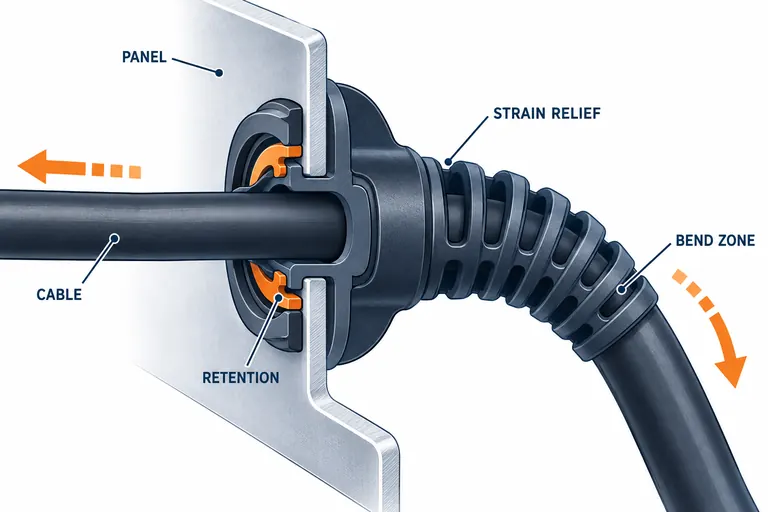
A cable grommet may look like a simple flexible molding, yet it often has to retain in a panel, protect a sharp edge, seal or deflect splash, guide assembly, and prevent cable loads from reaching a terminal. If those functions are blended into one vague requirement, the part can pass a visual sample review and still fail at the interface.
Define the panel, cable, load path, environment, and assembly sequence before selecting material or geometry. Separate edge protection, retention, bend relief, pull relief, and sealing requirements; then validate each function on production-intent cables and panels under the required environmental sequence.
Separate the functions before designing the shape
Edge-protection grommets isolate a cable from a hole or sheet-metal edge. Retention features keep the grommet in the panel. Strain relief transfers axial or torsional load away from conductors and terminals. Bend relief spreads curvature over a controlled length. Sealing features manage water, dust, vapor, or pressure. One component can perform several functions, but each needs its own load path and acceptance rule.
Create a function map for the exact installation. Identify panel material, hole profile, edge condition, thickness and tolerance; cable outside diameter, ovality, jacket material and tolerance; insertion direction; service access; routing angle; minimum bend radius; nearby heat, fluids and abrasion; and consequences of dislodgement or leakage.
HellermannTyton’s grommet guidance distinguishes pass-through edge protection, strain relief, and bend protection, and identifies cable diameter, panel hole, and panel thickness as basic selection dimensions (HellermannTyton cable grommets). For a custom automotive component, add the customer’s load, environmental, material, flammability, and validation requirements.
Avoid assigning an ingress rating to the grommet in isolation unless the specified test applies to the complete installed assembly. Hole finish, cable jacket, compression, mating enclosure, and installation all affect leakage. Likewise, a flexible boot that limits bending may not provide axial strain relief unless it mechanically grips or anchors the cable.
Define every side of the panel and cable interface
The drawing should show the panel cutout, edge radii or burr limits, thickness range, coating, and which side receives assembly. Include surrounding clearance for insertion tools and finger access. A retention lip designed to nominal panel thickness may be loose at one limit and impossible to seat at the other.
For the cable, provide jacket manufacturer/material where controlled, diameter range, roundness, surface texture, hardness, print or rib features, and whether the cable can migrate relative to the grommet. If multiple cable sizes use one part, define which functions apply at each diameter. Do not assume an elastomer will seal and grip a broad range without testing.
Use an interface table in the RFQ:
| Interface | Input to define | Acceptance evidence |
|---|---|---|
| grommet to panel | cutout, thickness, burr, coating, tolerance | insertion force, seated position, push-out/pull-out and rotation |
| grommet to cable | jacket, diameter, tolerance, surface | pull/slip, twist, compression and visible damage |
| cable bend | route, bend direction, available length | bend radius, cyclic flex or vibration where required |
| environmental path | splash, immersion, dust, temperature, fluids | assembly-level test with stated sequence |
| assembly process | manual/automatic method, access and poka-yoke | cycle demonstration and misassembly detection |
Inspect tolerance combinations, not only nominal samples. A thick panel and large grommet can produce excessive insertion force; a thin panel and small grommet can reduce retention. The cable and panel often come from different suppliers, so ownership of limit samples must be explicit.
Select material by deformation, environment, and process
Elastomer choice must balance insertion flexibility, retention recovery, bend support, abrasion, tear, compression set, temperature, fluids, UV, emissions, color, and processability. Hardness is only one descriptor. Two compounds with the same Shore hardness can differ in tensile behavior, tear, compression set, low-temperature flexibility, adhesion, and aging.
Candidate families may include TPE, TPV, TPU, silicone, EPDM or flexible PVC depending on duty and process, but no family is universally appropriate. Check the exact grade against cable-jacket compatibility, panel coating, automotive substances, flammability or interior-emission rules, and customer material specifications. If overmolded onto the cable, confirm whether adhesion is required and whether a mechanical anchor is used.
Temperature extremes can change both modulus and assembly force. A soft room-temperature part may become stiff in cold service or lose retention after hot aging. Fluid absorption can swell the grommet or alter friction. Compression set can reduce sealing load. UV and ozone matter for exposed elastomers. Request producer data with test conditions, then identify gaps requiring part-level tests.
Processing route also matters. Injection-molded TPE, compression-molded rubber, liquid silicone, and cable overmolding impose different tooling, cure, insert handling, flash, and cycle considerations. State whether the cable can tolerate process temperature and pressure. Material approval must include color and additive package, not just polymer type.
Design the load path and bend transition
Axial pull should be transferred through a defined grip, clamp, crimp, interlock, or housing anchor before reaching electrical termination. A soft overmold wrapped around a smooth jacket may slip. A panel grommet that retains strongly in the hole may still let the cable move. Map the force path from cable to grommet, grommet to panel, and cable to terminal.
Bend relief should create a gradual stiffness transition. A very short or stiff boot moves the hinge point to its end and can concentrate fatigue. Rib spacing, root radii, wall thickness, length, and cable clearance influence curvature. The preferred geometry depends on available envelope and required motion; more ribs are not automatically better.
SAE J1292 describes general vehicle wiring practices including grommet protection where conductors pass through metal and strain relief near terminals. Apply the customer’s current requirements and component specification rather than treating general guidance as a universal acceptance standard (SAE J1292 document).
Review mold parting lines and gates near sealing or flex zones. Flash can cut a cable or prevent seating; gate vestige can interfere with the panel. Avoid thin retention features that tear during demolding. If the design relies on undercuts, confirm ejection strain and recovery after aging.
Validate installation, retention, sealing, and durability in sequence
Measure molded parts and material condition, then assemble across panel and cable tolerances. Record insertion force and verify full seating. Test axial pull, push-out, rotation, cable slip, and bend behavior in the specified directions. Use the production assembly method and tools; hand-fitting a lubricated laboratory sample may hide a line issue.
Environmental tests should preserve the assembly state. Apply heat, cold, humidity, fluids, vibration, flexing, or splash in the customer-defined order, then repeat functional checks. Examine panel retention, cable jacket damage, cracks, permanent set, interface gaps, and terminal or conductor loads. If sealing matters, identify the actual leakage path and test pressure or spray arrangement.
For a cable passing through a coated bracket, tolerance analysis may show that insertion is highest with the thickest panel and largest retention bead, while push-out is lowest with the thinnest panel and smallest bead. Build limit combinations or controlled samples to evaluate both. Add cable-diameter limits for slip and bend tests. This is more informative than ten nominal assemblies.
Define inspection and reaction rules for flash, incomplete fill, surface damage, wrong material, incorrect seating, and retention failures. Keep cavity and material lot traceability through validation. If lubrication is permitted during installation, specify type, amount, location, and compatibility.
Give suppliers a complete RFQ package
Include CAD, a controlled drawing, panel cutout and thickness limits, panel coating, cable specification and diameter range, harness routing, available envelope, load directions, temperature and fluid profile, sealing need, color, annual volume, assembly process, tests, sample quantities, PPAP scope, and required declarations. Supply mating samples or limit gauges where drawings do not capture flexible interfaces.
Ask the supplier to return exact material, process route, parting/gate concept, tolerance concerns, insertion and retention assumptions, test ownership, fixture needs, tool maintenance, and exclusions. Keep this topic separate from a cable-routing clip RFQ, which focuses on bundle and attachment routing rather than a through-panel or cable-exit interface.
For replacement or second-source work, provide approved samples and failure history but do not ask the supplier to copy an unknown compound by appearance. Identify the polymer and grade through controlled records where possible, measure the real interface, and decide which tests must be repeated. Aging can make an old sample harder or smaller than its original state, so reverse engineering should preserve uncertainty rather than convert one used part into nominal material data.
Conclusion
Treat a grommet as an interface system with separate edge, retention, pull, bend, and sealing functions. Send AutoMoldingPro the CAD, panel and cable specifications, route, loads, environment, annual volume, and validation plan through the contact page for DFM and quotation review.