
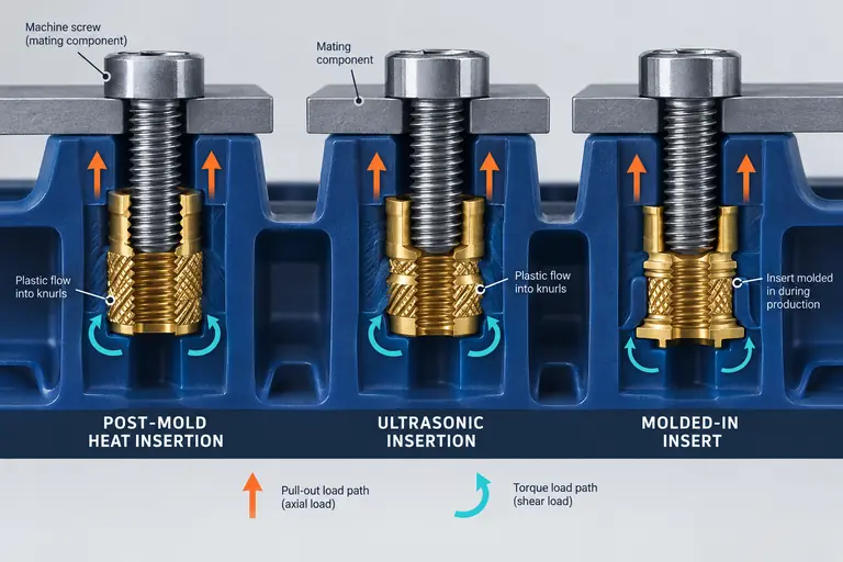
A metal insert can provide a reusable thread, but it does not automatically make a plastic joint strong. The insert may pull out, rotate, crack its boss, sit proud, tilt during installation, or be jacked out when the screw bottoms. These failures usually involve the insert, polymer, boss, mating part, fastener and installation process as one load path.
Select the insert and installation method only after defining service and assembly loads, access, material condition and production sequence. Then design the hole and surrounding plastic to the insert supplier’s current guidance, support the joint through the mating component, control installation depth and energy, and validate pull-out, torque, clamp retention and environmental conditioning on production-intent parts. Catalog performance is comparative evidence, not a guaranteed part result.
Translate the assembly into load cases
Draw the complete joint in section. Mark clamp load, service tension, shear, bending moment, vibration direction, thermal movement, removal cycles and the consequence of a loose fastener. Decide whether the insert carries load directly or only supplies threads while a shoulder, pilot or mating face carries shear. A screw that bottoms in a blind insert can convert tightening torque into axial jack-out rather than useful clamp load.
Define the fastener grade, thread, engagement, tightening strategy, mating-hole clearance and service access. If technicians may repeatedly remove the cover, include reuse cycles and damaged-thread recovery in the validation plan. If sealing depends on clamp load, evaluate compression distribution and relaxation across temperature, not only initial tightening torque. A metal thread resists stripping, but the surrounding thermoplastic can still creep or crack.
Choose an installation route that fits the polymer and production sequence
Post-mold heat insertion conducts heat through the insert and allows controlled displacement of thermoplastic into external knurls. Ultrasonic insertion generates localized heat through vibration and can be fast, but horn design, rigid fixturing, amplitude, pressure and polymer behavior matter. Molded-in inserts avoid a secondary insertion operation yet add loading, location, contamination and mold-damage risks. Press-in and self-tapping styles have their own stress and material limits.
SPIROL’s comparison notes that heat and ultrasonic methods apply to thermoplastics because the surrounding material is locally remelted. It also explains why external features need sufficient plastic flow for retention. Do not turn a supplier comparison table into a universal rule. Filled polymers, semi-crystalline behavior, nearby electronics, insert mass, access, cycle target and automation can change the preferred method. Require the insert manufacturer’s guidance for the selected series and the exact host material.
Design the boss, hole and mating interface together
Use the insert supplier’s recommended molded-hole geometry as the starting point, including diameter, taper, lead-in, depth, insert orientation and permissible draft. Provide space for displaced polymer and keep the screw from bottoming. Boss outside diameter, wall transitions, ribs, knit-line location and distance to a free edge influence cracking and retention. A thick isolated boss may sink on a visible surface; a thin boss may expand or split during installation.
The mating part should bear on stable plastic or a designed insert flange rather than pulling the insert through an oversized clearance hole. Control perpendicularity and positional tolerance to avoid cross-threading or side-loading. Where several inserts locate one rigid component, analyze true-position and compliance so the assembly is not overconstrained. Keep weld lines and gate decisions in the DFM review, because a weak knit line through the boss can dominate pull-out performance regardless of insert catalog rating.
Control installation as a joining process
Specify orientation, pre-placement, support nest, tip or horn, travel stop, force or energy controls, insertion rate, target depth, cooling or hold time and rejection criteria. Monitor the variables the selected equipment can control and verify the resulting joint rather than accepting a machine recipe alone. A flush target needs a functional tolerance related to mating-part seating, not an arbitrary appearance statement.
Section early samples to examine plastic flow around knurls and undercuts, cracking, voids and boss distortion. SPIROL’s design guide recommends cross-section evidence because retention depends on the plastic conforming to insert features. Also check thread contamination and install a representative fastener. For automated placement, add presence, orientation and depth detection plus mistake-proofing for wrong insert variants.
Validate the joint under relevant conditioning
Start with dimensional and visual checks, installation force or energy trends, thread gauging where required, pull-out and rotation resistance. Add tightening torque, clamp-load retention, repeated assembly, vibration, thermal cycling, humidity, fluid exposure or aging when those conditions represent service. Test the assembled load path; a standalone pull test can miss mating-part deformation, eccentric loading or sealing loss.
Define the specimen material lot, molding process, cavity, conditioning, install age and test fixture. Failure mode is as important as the peak value: insert rotation, axial extraction, boss fracture, thread failure and mating-part slip suggest different actions. Use project-specific acceptance criteria from the drawing and validation plan. Do not copy catalog values or another polymer’s result into the drawing as a universal minimum.
Evidence worksheet for the sourcing or release review
Use the worksheet as a traceability index, not a box-ticking score. For every line, record the source document, revision, owner, result, open action and approval authority. A missing item should remain visibly open until the responsible function decides whether it blocks quotation, tooling, sampling or production.
| Evidence line | What the reviewer should be able to verify |
|---|---|
| 1. joint section with clamp and service load paths | The record identifies the applicable product and process state, shows who created or accepted it, and supports the decision without relying on an undocumented conversation. |
| 2. exact insert series, material and revision | The record identifies the applicable product and process state, shows who created or accepted it, and supports the decision without relying on an undocumented conversation. |
| 3. resin grade, filler and conditioned state | The record identifies the applicable product and process state, shows who created or accepted it, and supports the decision without relying on an undocumented conversation. |
| 4. molded hole and boss inspection data | The record identifies the applicable product and process state, shows who created or accepted it, and supports the decision without relying on an undocumented conversation. |
| 5. installation equipment, nest and controlled settings | The record identifies the applicable product and process state, shows who created or accepted it, and supports the decision without relying on an undocumented conversation. |
| 6. sectioned samples showing plastic flow | The record identifies the applicable product and process state, shows who created or accepted it, and supports the decision without relying on an undocumented conversation. |
| 7. torque, pull-out and rotation test definitions | The record identifies the applicable product and process state, shows who created or accepted it, and supports the decision without relying on an undocumented conversation. |
| 8. environmental and repeated-assembly results | The record identifies the applicable product and process state, shows who created or accepted it, and supports the decision without relying on an undocumented conversation. |
How to challenge the evidence rather than merely collect it
- joint section with clamp and service load paths: Confirm the controlling revision, scope and owner. Compare the record with the current CAD, drawing and purchase baseline; a technically correct document from an obsolete state cannot support release. Record discrepancies as actions rather than silently choosing one source.
- exact insert series, material and revision: Check how the item was produced and whether the conditions match the quoted or released process. Identify substitutions, missing lots, different sites and temporary settings. Decide whether each difference is irrelevant, needs analysis, or requires new physical confirmation.
- resin grade, filler and conditioned state: Verify that the evidence represents every relevant cavity, variant and time period. A convenient sample may demonstrate possibility but not production coverage. Preserve identifiers so a later failure can be traced without reconstructing the population from memory.
- molded hole and boss inspection data: Review the measurement or observation method. The fixture, conditioning, instrument, software, operator rule and acceptance boundary must be suitable for the decision. Calibration alone does not prove that the method measures the intended feature without bias.
- installation equipment, nest and controlled settings: Look for interactions with assembly and downstream operations. A result that passes on a loose molding can change after fastening, welding, potting, conditioning, packaging or transport. Include those interfaces when they are part of the requirement.
- sectioned samples showing plastic flow: Ask what happens when the input moves toward a credible limit. Evidence only at a favorable nominal condition may hide fragility. Use planned boundary checks where justified, while respecting machine, material, tool and safety constraints.
- torque, pull-out and rotation test definitions: Define the disposition authority and the next gate. Supplier engineering may recommend an action, but customer approval, product engineering or quality may control release. The record should say what is accepted, what remains open and what blocks shipment.
- environmental and repeated-assembly results: Carry the conclusion into production documents. Update the setup, inspection, traceability, maintenance and change-control records that operators actually use. Retain the underlying evidence so future changes can be assessed against the same baseline.
Read the rows in sequence. The first items establish what is being judged; the middle items show how the product or process was created and measured; the final items connect evidence to release and future control. If two records conflict, resolve the revision and scope before averaging data or accepting the more convenient statement. Keep assumptions separate from verified facts, and convert accepted assumptions into controlled project inputs before irreversible tooling or shipment.
Questions that expose weak assumptions
| Question | A useful supplier answer should include |
|---|---|
| What failure mode is the joint designed to prevent? | A specific condition, responsible owner, supporting record, exception path and the evidence required before the next gate. |
| Why does this insert style suit the exact polymer? | A specific condition, responsible owner, supporting record, exception path and the evidence required before the next gate. |
| How is screw bottoming and insert jack-out prevented? | A specific condition, responsible owner, supporting record, exception path and the evidence required before the next gate. |
| Which installation outputs are monitored for each part? | A specific condition, responsible owner, supporting record, exception path and the evidence required before the next gate. |
| How are depth, tilt, cracks and thread contamination detected? | A specific condition, responsible owner, supporting record, exception path and the evidence required before the next gate. |
| Which conditioning and failure mode define acceptance? | A specific condition, responsible owner, supporting record, exception path and the evidence required before the next gate. |
Ask these questions in a joint engineering, quality and purchasing review. A technically detailed answer is still incomplete if it does not identify the controlled revision or who may authorize an exception. Likewise, a certificate or test report is weak if its samples, conditions and product state cannot be connected to the quoted or released part. Record the disposition beside the affected requirement so later teams do not have to reconstruct intent from email.
How the framework changes a real decision
For a cover that is removed during service, an insert is selected because the thread must survive repeated assembly. The first concept still fails review because the rigid mating bracket has tight holes across four inserts and the screws can bottom in the blind threads. The team enlarges the bracket clearances within location needs, defines usable thread depth, supports shear at locating features, and validates clamp retention after thermal exposure. The insert decision remains, but the joint becomes testable and tolerant of production variation.
The important step is to preserve the chain from requirement to evidence to disposition. If a condition changes—material, cavity, fixture, supplier, site, software, environment or customer scope—review which link in that chain is no longer valid. Do not restart every activity automatically, but do not assume the old conclusion transfers. State the delta, assess its mechanism, and agree the proportionate confirmation before release.
What to send for a project-specific review
Send the current STEP file and drawing, applicable material and customer specifications, annual and release quantities, assembly interfaces, identified critical or cosmetic characteristics, validation requirements, and any existing issue evidence. Use the AutoMoldingPro automotive project RFQ to keep the files and decisions tied to one revision. The review should identify missing inputs and acceptance responsibilities before tooling or production commitment; it cannot replace customer approval.
Link joint results back to drawing and production control
Identify the approved insert series or controlled functional specification, thread, usable depth, orientation, installed-height tolerance and surrounding molded-hole requirements. Put assembly torque and destructive tests in the documents owned by the appropriate functions. Similar knurl appearance does not establish equivalence.
Production controls should detect the input and the result. Incoming checks verify insert identity; molding checks verify boss and hole; installation controls monitor presence, orientation, travel and selected equipment outputs; finished checks verify seating, thread condition and planned destructive samples.
Classify failures before changing settings. Cracked bosses point toward hole size, residual stress, material, energy or geometry. Low pull-out with intact plastic may indicate poor flow into retention features. Rotation, clamp loss, cross-threading and proud seating each direct investigation toward different interfaces.
Section representative failures and compare them with conforming joints. Update the mold drawing, insert specification, installation program, nest and inspection plan together. A correction is not durable when only the machine recipe changes and the product definition still permits the failed condition.
Link joint results back to drawing and production control
Identify the approved insert series or controlled functional specification, thread, usable depth, orientation, installed-height tolerance and surrounding molded-hole requirements. Put assembly torque and destructive tests in the documents owned by the appropriate functions. Similar knurl appearance does not establish equivalence.
Production controls should detect the input and the result. Incoming checks verify insert identity; molding checks verify boss and hole; installation controls monitor presence, orientation, travel and selected equipment outputs; finished checks verify seating, thread condition and planned destructive samples.
Classify failures before changing settings. Cracked bosses point toward hole size, residual stress, material, energy or geometry. Low pull-out with intact plastic may indicate poor flow into retention features. Rotation, clamp loss, cross-threading and proud seating each direct investigation toward different interfaces.
Section representative failures and compare them with conforming joints. Update the mold drawing, insert specification, installation program, nest and inspection plan together. A correction is not durable when only the machine recipe changes and the product definition still permits the failed condition.
Link joint results back to drawing and production control
Identify the approved insert series or controlled functional specification, thread, usable depth, orientation, installed-height tolerance and surrounding molded-hole requirements. Put assembly torque and destructive tests in the documents owned by the appropriate functions. Similar knurl appearance does not establish equivalence.
Production controls should detect the input and the result. Incoming checks verify insert identity; molding checks verify boss and hole; installation controls monitor presence, orientation, travel and selected equipment outputs; finished checks verify seating, thread condition and planned destructive samples.
Classify failures before changing settings. Cracked bosses point toward hole size, residual stress, material, energy or geometry. Low pull-out with intact plastic may indicate poor flow into retention features. Rotation, clamp loss, cross-threading and proud seating each direct investigation toward different interfaces.
Section representative failures and compare them with conforming joints. Update the mold drawing, insert specification, installation program, nest and inspection plan together. A correction is not durable when only the machine recipe changes and the product definition still permits the failed condition.
Conclusion
Base the decision on a defined product state, controlled inputs, traceable evidence and an explicit release authority. Keep exceptions visible, preserve the conditions behind every result, and require the supplier to explain how the conclusion will remain valid in production. That approach turns a broad technical request into an auditable manufacturing decision.