
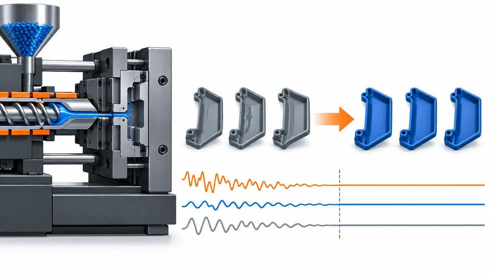
Startup parts can look acceptable while the mold, melt and process are still moving toward equilibrium. Releasing those parts too early mixes warm-up effects with normal production and makes later dimensional or appearance drift difficult to explain. Rejecting every early shot by habit is not a control either: it hides why scrap occurs and prevents a repeatable release decision.
A stable first-off condition should be defined by verified setup inputs, an agreed warm-up and purge sequence, time-ordered process signals, representative parts from every required cavity, and product checks that meet the current control plan. The release point is reached only when the observed process and parts show no unresolved startup trend. The number of shots is evidence from the validated process—not a universal rule.
Define what “first-off” is allowed to release
Begin by separating three populations: deliberate purge or setup material, parts held while the cell approaches the approved state, and saleable production released after the startup criteria pass. The traveler or electronic batch record should identify the boundary. Otherwise a container can contain parts molded under different thermal, material and cavity conditions even if all of them look alike. Define whether first-off means the first complete shot, first inspected set, first conforming set, or first set after stability. For automotive supply, the useful definition is tied to the approved product and process state, not to the clock or the operator’s confidence. The long-gap restart guide covers the same boundary decision when a mold returns after months idle.
List the characteristics that can move during startup: part weight, fill time, transfer position, peak pressure, cushion, recovery time, mold-water supply and return, hot-runner behavior, dimensions, warpage, appearance, insert position and assembly function.
"No unresolved startup trend" needs numbers, not a feeling. John Bozzelli’s six-metric test for a lined-out process (Plastics Technology) gives the tolerances to check before release:
| Metric | Stable means | Bozzelli’s tolerance |
|---|---|---|
| Fill time | Constant from shot to shot | Within ±0.04 s for most jobs |
| Pressure at transfer | Varies within a range, does not trend | Range set from process-development data for this part |
| Cushion (at end of hold) | Stable | Within ±1–1.5 mm |
| Screw recovery time | Stable shot to shot | Within ±2% |
| Cycle time | Consistent | No drift; use an overall cycle timer if it is operator-dependent |
| Part temperature | Stops trending | Within ±~10 °F (5 °C), measured at the same spot |
Fill time should be stable within three to five shots; if it is not, something is wrong. Pressure at transfer will trend up or down during warm-up — that trend is expected — but once the process is stable it should vary within a range and stop trending. A first-off set released while fill time or part temperature is still trending is a set released on hope, not on evidence.
Select signals because they connect to the part, not because the machine displays them. The run-at-rate article explains a different decision—sustained capacity under production conditions. Routine first-off release is narrower, but its baseline should still be consistent with the validated production setup.
Verify the cell before judging molded parts
A first-off checklist starts before resin enters the cavity. Confirm the mold and revision, press, screw and non-return condition, hot-runner controller, thermolators, water routing, core and valve-gate sequence, robot or handling program, fixture revision and inspection equipment. Check the released material manufacturer, complete grade, color and lot; verify storage and drying records where the resin requires control. Startup scrap caused by the wrong color, a closed water circuit or an obsolete robot program cannot be corrected by waiting for more cycles.
The startup sequence should specify how residual material is removed and where purge is contained. Heat-sensitive or incompatible materials need a documented shutdown/startup approach based on the resin and hot-runner suppliers’ instructions. Write the actual cell sequence around the approved mold, resin and equipment. Record deviations instead of silently compensating with temporary settings.
Use time-ordered evidence to detect stability
Do not average the whole startup into one result. Plot or review selected signals in shot order and preserve cavity identity. A downward fill-time trend, rising mold-return temperature, saw-tooth recovery behavior or step after an operator change means the process has a time structure that a simple average conceals. RJG’s explanation of process stability distinguishes random variation from trend, cycle and step patterns; that distinction is more useful than adopting a fixed number of warm-up shots.
Choose a review window long enough to expose the mechanism relevant to the cell. A small tool may reach thermal equilibrium quickly, while a large mold, hot runner or thick insert can continue changing after visually good parts appear. Compare actual values with the approved setup and any established startup envelope. Stability does not mean zero variation, and conformance does not prove stability. The release decision needs both: no unresolved non-random movement in the chosen signals and parts that satisfy the current acceptance requirements. If the process remains directional, continue holding parts and investigate the cause. During validation, compare labeled parts after representative short and long interruptions to establish the restart checks for this cell. RJG’s temperature-stabilization example shows why a pressure trace within alarms can still miss a thermally driven dimensional change.
Sample cavities and characteristics without cherry-picking
For multi-cavity molds, take an identified set from every active cavity at the defined release point. If parts are handled in a family stack, maintain orientation so a weak cavity cannot be lost in pooled results. Match the check to startup risk: weight and appearance may be rapid screens, but a datum shift, seal fit or critical clip function may need a fixture or measurement defined by the control plan. Do not substitute a convenient visual check for a characteristic that determines assembly.
Sampling one especially good shot after a series of poor parts creates false confidence. Define whether the release set is consecutive, how many cycles it spans, who inspects it and what happens after a failure. Keep previous startup parts segregated until their disposition is clear. If measurement requires conditioning or laboratory time, identify which fast checks permit provisional containment and which results are required before shipment. A provisional internal release is not the same as customer product approval, and the rule must follow the program’s requirements.
Write a reaction plan for failed startup evidence
A useful reaction plan classifies the failure before adjustment. Wrong material, missing traceability or an incorrect tool setup requires containment and correction of the input. A thermal trend requires continued stabilization or investigation of water, heaters or cycle. Cavity-specific flash or short shot points toward local tool, vent, gate or balance evidence. Random weight and cushion movement may lead to material feeding, check-ring or machine checks. Each branch should state who can change what and which evidence must be repeated.
Avoid changing temperature, speed, transfer, hold and clamp force together. One-factor or deliberately designed trials preserve cause and effect and prevent a temporary setting from becoming the new undocumented standard. After correction, restart the release window; do not splice favorable observations from before and after the change. If the approved process can no longer achieve stable, conforming parts, escalate to maintenance, engineering or customer change control instead of widening limits at the press.
Convert startup findings into prevention
Track startup scrap by reason and cell event, not only by total weight. Separate planned purge, color/material transition, thermal hold, setup error, equipment fault, tool contamination and failed first-off.
Record each startup against the table below, not only by total weight. One row per start; the "first check" column is the decision the article’s prose does not make — it names the single check that closes that reason code.
| Reason code | What counts here | Shots / kg | First check | Owner |
|---|---|---|---|---|
| Planned purge | [ ] | [ ] | [ ] | [ ] |
| Color / material transition | [ ] | [ ] | [ ] | [ ] |
| Thermal hold | [ ] | [ ] | [ ] | [ ] |
| Setup error | [ ] | [ ] | [ ] | [ ] |
| Equipment fault | [ ] | [ ] | [ ] | [ ] |
| Tool contamination | [ ] | [ ] | [ ] | [ ] |
| Failed first-off | [ ] | [ ] | [ ] | [ ] |
Compare repeated starts of the same mold in this table, not in a weight total: a startup that is always "thermal hold" points at the warm-up sequence, while a startup that is always "failed first-off" points at the release criteria.
The categories should be simple enough to use but specific enough to direct action. Compare repeated starts of the same mold to identify persistent delays, then verify corrective action on a later start. A single fast startup does not prove the new method is robust.
Update the setup sheet, hose map, purge sequence, robot recipe, first-off checklist or maintenance trigger where the evidence belongs. Preserve the successful release state, including material lot, cavity map and time-ordered signals. The objective is not to drive startup scrap to a rhetorical zero; it is to make unavoidable transition material visible, reduce preventable loss, and stop unverified parts from entering production. A long shutdown, major repair or obsolete approval state may require the broader requalification described in restarting a program after a long gap.
Stable first-off release worksheet
Complete the worksheet at the proposed first-saleable-shot boundary. Link the time-ordered stability window to the inspected cavity set and keep all earlier material under its recorded disposition.
| Review line | Required input or evidence | Decision test |
|---|---|---|
| Product baseline | Part/drawing revision, approved sample state and current acceptance plan | All references agree; obsolete or missing approvals are escalated before molding |
| Material state | Manufacturer, full grade, color, lot, drying/handling and prior barrel material | Identity and preparation match the released process |
| Cell setup | Press, tool, water map, hot runner, core/valve/robot programs and fixtures | Actual setup matches controlled records; deviations are documented |
| Stability window | Time-ordered fill, transfer, pressure, cushion, recovery, cycle and thermal signals | No unexplained trend, cycle or step in the agreed review window |
| Part set | Consecutive, cavity-identified parts and required quick/functional checks | Every required cavity passes; no cherry-picked shot |
| Release and segregation | Release time/shot, held quantity, scrap reason and approver | The first saleable unit and earlier disposition are traceable |
Illustrative example
A four-cavity connector cover produces visually acceptable parts ten cycles after startup, but return-water temperature is still rising and cavity 4 part weight drifts upward. The team keeps those parts in startup hold, verifies the water routing, and discovers a restricted circuit on the cavity-4 side. After restoring flow, it repeats the consecutive cavity-identified set and sees stable process signals before dimensional release. The decision prevents early parts from being mixed with the stable lot without inventing a universal warm-up count.
Questions to ask the supplier before the next gate
Which observed signals demonstrate that this cell has stopped trending?
Show shot- or time-ordered traces for the selected fill, pressure, cushion, recovery and thermal signals over the cell’s validated review window. Mark interruptions and adjustments, retain cavity identity where measured, and investigate unexplained trends, cycles or steps. Confirm the associated part checks also pass; stable signals alone do not release nonconforming parts.
How are startup, held and released parts physically and electronically separated?
Show distinct containers and status labels, matching batch-record states, and the release time or shot boundary. Record the quantity and disposition of earlier parts so held material cannot be mixed into the released lot. Identify who may change the hold status.
Does the first-off set represent every active cavity and the required conditioned state?
Provide the cavity-to-sample map, the consecutive cycles selected and each required inspection result. Identify sample age, conditioning and any assembly state specified by the control plan. Keep release conditional where a required result is pending; do not replace an unmeasured cavity with a pooled average.
Which setup deviations require engineering or customer approval rather than an operator adjustment?
Identify the operator’s approved adjustment ranges and the escalation route for a different material, tool revision, equipment configuration or setting outside those ranges. Engineering must assess the change against the validated process and customer requirements; the program’s change-control rules determine whether customer approval is needed. Production urgency is not approval.
What evidence must be repeated after any startup correction?
Start a fresh stability window after the correction, then repeat the affected part checks and any coupled dimensions, appearance or functions that the change could disturb. Identify the first corrected sample set and keep earlier material segregated. Do not combine favorable readings from the two process states.
What to provide for a project-specific review
For a startup-control review, provide the current setup sheet, mold and material identity, cavity map, first-off checklist, critical characteristics and several time-ordered startup records. Include the observed failure, held quantity and last approved setup in the project inquiry.
References
- RJG explanation of process stability
- RJG on sampling after stabilization
- RJG on temperature recovery after interruptions
- AutoMoldingPro long-gap restart decision framework
- Plastics Technology (John Bozzelli), "How to Know When Your Process is Ready to Make Acceptable Parts" — six metrics for a lined-out, stable process: https://www.ptonline.com/blog/post/how-to-know-when-your-process-is-ready-to-make-acceptable-parts
- RJG, "Finding Correlations to Part Quality with eDARTs" — the "Four Plastics Variables" (melt temperature, flow rate, pressure, cooling): https://rjginc.com/wp-content/uploads/2008/04/Finding_Correlations_to_Part_Quality_with_eDARTs.pdf