
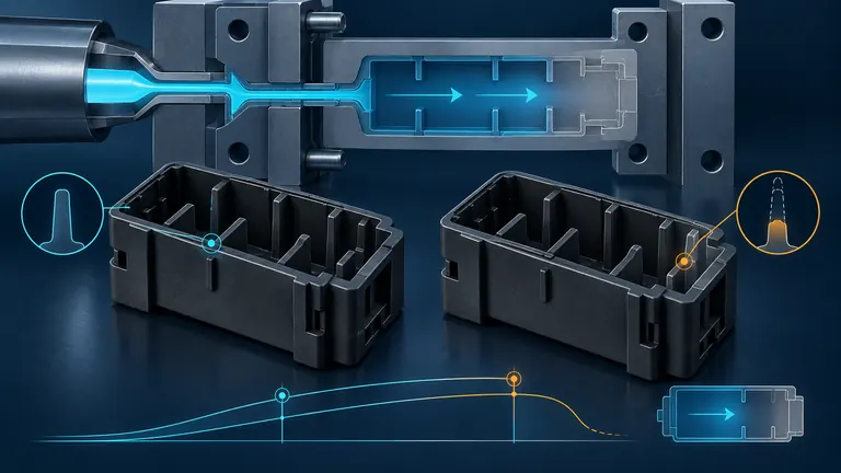
Conceptual illustration; not to scale.
A short shot is easy to name and surprisingly easy to misdiagnose. The missing plastic may come from an interrupted material supply, a leaking check valve, a frozen flow path, trapped air, a restrictive gate, or a pressure limit. Raising pressure before separating those causes can hide the evidence, create flash elsewhere, and move the defect without making the process reliable.
Start with the defect pattern and the evidence from the last stable run. Confirm that the machine delivered the intended shot, then determine whether the flow stopped at the same location, a particular cavity, or an intermittent point. Check supply and machine repeatability before changing temperatures or speeds; check pressure transfer and flow restrictions before modifying steel. Change one controlled factor at a time and keep the resulting part, process trace, and cavity identity together.
Preserve the failure before changing the process
The first useful action is not a process adjustment. It is to capture a reproducible description of the failure. A short shot that always ends at one thin rib suggests a different investigation from a random incomplete fill that moves between cavities. If the team loses that distinction, every later adjustment becomes difficult to interpret.
Quarantine representative parts and mark date, time, machine, mold, cavity, resin lot, color or additive lot, operator, and cycle position. Photograph the incomplete edge from the same angle and identify the last-filled location on a drawing or screen capture. Record whether the condition occurred at startup, after a material change, after an interruption, at a steady cycle, or only after the mold became hot. Also retain one complete part from the last known acceptable run if the traceability permits it.
Export the actual machine trend or cycle record rather than copying only setpoints. At minimum, preserve fill time, screw recovery time, cushion, transfer position or pressure, peak injection pressure, injection speed stages, melt and mold temperature readings, and alarm history. A stable setpoint can coexist with an unstable delivered shot if material feed, screw recovery, the non-return valve, or a machine limit has changed.
Before anyone opens a gate, vent, or hot-runner component, record its current condition. Look for blocked vents, resin at the parting line, gate damage, heater or thermocouple alarms, cooling interruption, and evidence of a stuck valve gate. The objective is not to declare a root cause from appearance. It is to prevent the investigation from erasing the condition that must be explained.
Use location and repetition to choose the first branch
Defect location is a diagnostic filter. When every cavity stops at a similar relative point, the common feed system, material condition, machine delivery, or process limit deserves early attention. When one cavity fails while others fill, inspect that cavity’s gate, runner balance, venting, local cooling, and moving components. When the incomplete area changes from shot to shot, investigate material supply and machine repeatability before cutting steel.
Create a simple pattern map:
| Observed pattern | First evidence to compare | Likely investigation branch | Do not assume |
|---|---|---|---|
| All cavities short at similar flow distance | Cushion, fill time, peak pressure, shot volume, material feed | Machine delivery or common flow restriction | More clamp force will improve filling |
| One cavity repeatedly short | Cavity pressure if available, gate/runner condition, vent witness, cavity temperature | Local gate, vent, balance, cooling or valve-gate issue | The resin is wrong for the whole mold |
| Failure moves between cavities | Screw recovery, feed consistency, check-valve repeatability, heater alarms | Intermittent machine, material or hot-runner condition | The first visible cavity is the root cause |
| Last-to-fill end is short with burn or gas mark | Fill pattern, air-trap prediction, vent condition | Trapped gas or inadequate vent path | Faster injection is always safer |
| Thin branch freezes while thicker path fills | Fill-time pattern, wall transition, gate location, mold temperature | Hesitation, racetrack effect or thermal freeze-off | Higher pressure alone fixes the design |
Autodesk’s Moldflow troubleshooting guidance lists restrictions, hesitation, long flow paths, inadequate venting, low melt or mold temperature, insufficient delivered material, and machine defects as distinct short-shot causes. Its fill-time guidance also notes that hesitation can freeze a thin path before completion. These are categories for testing, not a menu of settings to increase together.
Use the table to decide what evidence to collect next. If the defect is cavity-specific, compare it with a neighboring cavity under the same shot. If it is system-wide, a local vent change is unlikely to explain the whole event. If the pattern is intermittent, first prove that the delivered material volume and screw behavior are repeatable.
Check material delivery and machine repeatability before the mold
A process cannot fill consistently if the machine does not deliver a consistent melt charge. Confirm the resin identity and approved grade, drying condition where applicable, regrind or colorant rule, hopper level, feed-throat condition, and material-conveying alarms. Do not infer correct drying from a dryer setpoint alone; use the resin supplier’s grade-specific instructions and the project’s approved process record.
Compare screw recovery time and end position across acceptable and short cycles. A changing recovery time can point to feed interruption, bridging, inconsistent bulk density, screw or barrel condition, or back-pressure effects. Compare cushion and transfer behavior. A cushion that collapses or varies can indicate an inconsistent shot or leakage across the non-return valve. A worn check valve may allow pressure or volume to leak, which Autodesk includes among machine-related causes.
Confirm that the programmed injection profile was actually achieved. A machine can reach a pressure limit before reaching the commanded velocity. In that case, the screen may show a speed setting that was never delivered. Review the trace for the point where velocity control became pressure-limited, and verify that the maximum pressure is appropriate for the machine, mold, resin, and approved process window. Do not simply increase the limit without checking tool protection, flash risk, and the cause of the additional resistance.
Check heaters, thermocouples, nozzle contact, nozzle orifice, and hot-runner zones against the approved setup. A cold or restricted nozzle can affect every cavity. A failed hot-runner zone may affect one branch. Verify actual temperature with the method authorized by the plant; a displayed value is not proof that heat is reaching the melt path correctly.
Only after material delivery and machine repeatability are credible should the team interpret a persistent mold-flow restriction.
Separate pressure limitation, thermal freeze-off, and trapped air
These three conditions can create a similar incomplete edge, but they require different corrective actions. Use the pressure and fill traces with part location rather than relying on one visual symptom.
For a pressure-limited fill, determine where the machine reaches its limit and whether the remaining flow length is plausible for the actual resin, wall, gate, and temperature. Look for an unexpected increase from the established baseline. A restriction may come from a damaged gate, blocked nozzle, cold slug, shifted component, contamination, or an unapproved geometry change. If the pressure has always been marginal, the original gate, runner, wall, or material selection may need engineering review.
For thermal freeze-off, compare mold temperature, melt preparation, actual fill time, and the geometry at the stopped front. Thin branches and abrupt thickness transitions can hesitate while a thicker path continues. Increasing temperature or speed may improve flow, but it can also alter degradation, flash, appearance, orientation, warpage, and cycle stability. Any change must stay within the resin supplier’s guidance and the approved process-development method.
For trapped air, inspect whether the short is at a last-to-fill location or where flow fronts converge. Autodesk describes air traps as compressed gas between converging fronts or between the front and cavity wall; inadequate venting can cause incomplete filling and may also produce burns or blemishes. Clean and measure vents against the mold record before enlarging them. Check whether the parting line is being sealed by contamination, damage, excessive clamp conditions, or a component that is not seating correctly.
Simulation can help identify fill pattern, hesitation, pressure demand, and likely air-trap locations, but it does not prove the current mold is clean, the valve gate is moving, or the machine delivered the modeled material state. Use analysis to form a testable hypothesis and compare it with the actual short-shot progression.
Run a controlled short-shot study instead of random adjustments
Once the first branch is selected, plan a small experiment that changes one factor while preserving all others. The purpose is to learn where the flow front moves and what machine response changes, not to make one cosmetically complete sample at any cost.
Use a staged fill or short-shot sequence only under an approved safe procedure. Identify each part by step and cavity. Record part weight, fill time, cushion, peak pressure, transfer point, and the observed flow front. If cavity pressure sensors are available and validated for the task, compare the arrival and pressure profile between cavities. If they are not available, do not invent equivalent data from the machine nozzle pressure.
Suggested diagnostic sequence:
- Reproduce the failure at the documented condition.
- Confirm material delivery, screw recovery, cushion, alarms, and actual injection profile.
- Compare cavities and locate the last stable flow front.
- Inspect common and cavity-specific gates, runners, valve gates, vents, and temperatures.
- Change one authorized variable within the approved processing range.
- Retain the resulting parts and traces, then decide whether the evidence supports process correction, maintenance, or design review.
Illustrative example: a four-cavity connector cover repeatedly shorts in cavity three at the same remote rib. The other cavities fill, and cushion and recovery remain stable. The team compares the gate and vent condition, finds that the cavity-three vent witness differs from the approved maintenance record, cleans and measures the vent, and repeats the same staged-fill sequence. The example does not prove every cavity-specific short is a vent problem; it shows how pattern evidence prevents an unrelated system-wide pressure change.
Define the release condition after the part fills
A complete-looking part is not the end of the investigation. The corrected condition must produce acceptable dimensions, appearance, assembly performance, and repeatability without creating flash, burns, overpacking, warpage, or an unsafe machine limit.
Document the confirmed cause, action, affected tool or process revision, trial evidence, and approval owner. Update the maintenance record if a vent, gate, heater, valve, or check component was serviced. Update the process-development record and control plan only through the project’s approved change route. If the correction changes part geometry, gate size, material, or an approved process condition, identify the customer notification and validation requirements before production release.
Ask the supplier for the failed and corrected traces, cavity-marked samples, part-weight comparison, maintenance record, dimensional or functional checks for affected features, and the defined reaction plan. For a recurring defect, request evidence across a representative run rather than one complete shot.
If your team needs an external assessment, provide the part drawing, resin grade, mold layout, cavity map, machine trend, defect photographs, frequency, and last known good condition through the automotive plastic injection molding service or request a production-problem review. A credible first response should define the evidence needed before promising a repair or recovery date.
Conclusion
Diagnose short shots in evidence order: preserve the pattern, verify delivered material and machine repeatability, separate common from cavity-specific causes, then test pressure, thermal, flow, and venting hypotheses one at a time. Release production only after the corrected condition fills repeatedly and the affected quality characteristics still meet the approved requirements.
References
- Autodesk Moldflow, Troubleshooting short shot problems — distinct short-shot causes and remedy categories.
- Autodesk Moldflow, Fill time result — interpreting hesitation, unfilled regions, weld lines and air traps in fill analysis.
- Autodesk Moldflow, Air traps result — relationship between converging flow fronts, venting and incomplete fill.
- DME, Injection molding troubleshooting — mold and machine checks that should be evaluated without treating one adjustment as universal.