
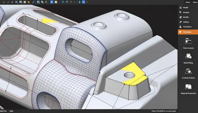
Dashboard components look simple on a CAD screen, yet they are among the most difficult automotive plastic parts to tool and produce. Large flat surfaces warp. Thick bosses sink. Cosmetic surfaces show every weld line and gloss shift. When a program manager underestimates these risks, the result is late T1 samples, painful mold rework, and delayed launches. Understanding how dashboard molding really works prevents these expensive surprises.
Injection molding is the dominant process for automotive dashboard panels1 because it produces complex geometries, integrated mounting features, and Class-A cosmetic surfaces at high volume with repeatable dimensions. Common parts include the instrument-panel substrate, cluster bezel, center-stack fascia, air-vent housings, and display surrounds. Typical materials are modified PP for large substrates and PC/ABS for dimensionally sensitive visible parts2. Success depends on wall-thickness control, gate placement, cooling design, and validated material selection.
In this article, I will walk through the materials, process choices, design rules, tooling, and quality controls that determine whether a dashboard molding program reaches stable production or gets stuck in rework. I will also cover the trade-offs I see most often when engineers try to integrate too much into one large part.
Why Is Injection Molding the Preferred Process for Dashboard Panels?
Some teams assume any large plastic part can be molded the same way. Then they discover that a one-meter dashboard substrate behaves nothing like a small clip. The part warps, the surface shows sink and gloss variation, and the mold costs far more than expected. Choosing the right process early avoids these late-stage shocks.
Injection molding is preferred for dashboard components because it combines complex geometry, integrated features, cosmetic surfaces, and dimensional repeatability at production volumes. No other process delivers this balance economically. For large or thick-walled structures, gas-assisted molding, sequential valve gating, and two-shot molding extend what injection molding can achieve, allowing weight reduction, weld-line control, and hard/soft material combinations within a single tool.
Where injection molding earns its cost
The tooling investment is high, but the per-part economics are strong once volumes reach thousands of units. A dashboard substrate can integrate the following into one molding:
- Instrument-cluster and display openings
- Air-vent apertures
- Fastener bosses and locating pins
- Snap fits, clips, and wire-routing channels
- Brackets for HVAC or electronic modules
Process variants that matter for dashboards
- Gas-assisted injection molding hollows out thick sections to reduce weight, minimize sink marks, and maintain rigidity in structural ribs.
- Sequential valve gating opens gates in a controlled sequence to eliminate visible weld lines on long flow paths.
- Two-shot and overmolding integrate a soft-touch skin over a rigid substrate in one process.
- In-mold decoration (IMD) applies a decorative or scratch-resistant film during molding, reducing secondary painting.
A common mistake I see is selecting a single simple molding approach for a complex dashboard and then paying for it later in warpage, weld lines, and rework. Decide the process strategy during DFM, not after the mold is cut.
Which Materials Are Best for Automotive Dashboard Components?
Material selection often gets rushed. A team copies a resin from a previous project without checking cabin temperature, emissions limits, or the OEM approved-material list. The mold then produces parts that warp under summer heat, fail odor testing, or cannot meet the appearance spec. This is one of the most costly mistakes in dashboard programs.
The most common dashboard materials are modified PP for large substrates and PC/ABS for dimensionally sensitive visible parts such as bezels and display surrounds. PP offers low density, low cost, and good chemical resistance. PC/ABS offers higher impact strength, better dimensional stability, and superior surface appearance. Talc-filled and glass-fiber-reinforced grades improve stiffness and heat resistance, but final selection must match the approved material datasheet and OEM requirements.
Material comparison for dashboard applications
| Requirement | PP (modified/filled) | PC/ABS | Glass-filled PP or PA |
|---|---|---|---|
| Density / weight | Low | Medium | Medium–high |
| Impact resistance | Good | Very good | Good |
| Heat / thermal stability | Moderate (improved with talc) | Good | Very good |
| Dimensional stability | Moderate | Good | Very good |
| Surface appearance | Fair–good | Very good | Fair |
| Relative material cost | Low | Higher | Medium |
| Typical use | Main substrate, vents | Bezels, fascia, display surrounds | Structural brackets, mounts |
Practical selection criteria
When I review dashboard material choices, I check these points before tooling:
- Peak cabin temperature exposure, especially near glass and vents
- Impact and head-impact safety requirements for the location
- Odor, fogging, and volatile-emission limits
- Scratch and mar resistance for touch surfaces
- Recyclability and any bio-based or recycled-content targets
- The OEM’s approved-material list and customer-specific requirements
Recycled and bio-based PP content is increasing as automakers pursue lightweighting and sustainability goals. This can be practical, but flow behavior, color consistency, and mechanical performance must be revalidated. Never assume a recycled grade drops in without testing. Always verify the final choice against the approved drawing, the material technical datasheet, and the customer-specific requirements.
How Do You Control Warpage and Cosmetic Defects on Large Dashboard Panels?
Warpage is the defect that ends careers on dashboard programs. A large flat panel with uneven wall thickness or unbalanced gates will twist off the fixture, and no process tweak fully fixes a bad design. Cosmetic defects such as sink, weld lines, and gloss variation are equally damaging on Class-A surfaces because they cannot be hidden.
Warpage and cosmetic defects are controlled primarily through uniform wall thickness, balanced gate placement, optimized packing pressure, and uniform cooling. Ribs should be about 50–60% of the nominal wall to avoid sink. Gates should stay away from visible surfaces. Mold-flow simulation should predict fill, weld lines, and warpage before the tool is built. Design fixes are far cheaper than process compensation later.
Design rules that reduce warpage
- Maintain relatively uniform nominal wall thickness across the part.
- Core out thick solid sections instead of adding mass.
- Use generous radii at corners and transitions.
- Add ribs for stiffness rather than increasing wall thickness.
- Balance the filling pattern so no region shrinks dramatically differently.
Common cosmetic defects and corrective actions
| Defect | Likely cause | Typical correction |
|---|---|---|
| Warpage | Uneven wall, unbalanced fill, uneven cooling | Improve wall uniformity, rebalance gates, optimize cooling |
| Sink marks | Thick bosses or ribs, low packing | Core out thick sections, reduce rib thickness, improve packing |
| Weld lines | Flow fronts meeting around openings | Relocate gates, use sequential valve gating, add venting |
| Gloss/texture variation | Uneven cooling, unstable process | Balance cooling, stabilize conditions, refinish inserts |
| Ejection whitening | Low draft, high ejector load | Increase draft, improve cooling, relocate ejectors |
The role of cooling design
Conformal cooling channels, produced through additive manufacturing, deliver more uniform heat extraction across complex dashboard tooling. This shortens cycle time and reduces surface and dimensional variation. On large parts with thick or awkward sections, conformal cooling can be the difference between a stable process and constant warpage fighting. Discuss cooling strategy during mold design, not after T1 shows distortion.
What Tooling and Draft Requirements Apply to Dashboard Molds?
Dashboard tooling is large, expensive, and unforgiving of design mistakes. Teams sometimes approve a mold quotation based on price alone, then discover the tool lacks proper cooling, adequate venting, or replaceable inserts in wear areas. Fixing these problems after cutting steel is slow and costly.
Dashboard molds typically require hot-runner or valve-gated systems, multiple balanced gates, extensive cooling circuits, replaceable cosmetic inserts, robust ejection, and slides for undercuts. Every surface pulled in the opening direction needs draft, roughly 0.5–1° per side for smooth surfaces and more for textured Class-A grain. Ejectors must sit on non-cosmetic areas supported by internal structure to avoid whitening or deformation during ejection.
Key tooling features to confirm before approval
- Hot-runner or valve-gated injection system suited to the flow length
- Multiple gates positioned for balanced filling
- Distributed cooling circuits, including conformal cooling where needed
- Replaceable cavity inserts in high-wear or cosmetic areas
- Hydraulic or servo slides for undercuts and apertures
- Robust ejector layout on non-visible surfaces
- Documented mold steel, cavity count, and expected mold life
Machine selection
The required clamp force depends on projected part area, material, gate strategy, and cavity count, not part weight alone. A large substrate needs a much larger machine than a small bezel. I always base machine selection on the mold-flow study and the machine manufacturer’s clamp-force calculation. Undersizing the machine causes flash and short shots; oversizing raises cost without benefit.
A modular versus integrated decision
Integrating every feature into one large molding increases mold complexity, service difficulty, and dimensional risk. A modular architecture, such as a PP substrate plus a separate PC/ABS bezel, often produces better appearance and lower total risk when parts need different materials, finishes, or tolerances. Do not chase part-count reduction at the expense of moldability and quality.
What Quality and Compliance Requirements Apply to Dashboard Parts?
Dashboard components carry safety and appearance responsibilities that many teams underestimate. Passing dimensional inspection is not enough. If the material fails flammability, emissions, or heat-aging tests during validation, the entire program stalls while you re-source or re-qualify material.
Dashboard validation goes well beyond dimensions. A production control plan usually includes first-article and CMM dimensional inspection, appearance and gloss checks, impact and heat-aging tests, thermal cycling, scratch and chemical resistance, odor and emission testing, clip-retention checks, and flammability testing. In the United States, interior occupant-compartment materials must meet FMVSS No. 302, which limits horizontal flame propagation to no more than 4 inches per minute, about 102 mm/min.
Validation checklist before mass production
- First-article dimensional report against the approved drawing
- CMM or 3D-scan results for critical dimensions and GD&T
- Color, gloss, grain, and appearance approval
- Impact, heat-aging, thermal-cycling, and humidity results
- Scratch, abrasion, and chemical-resistance data
- Odor and volatile-emission testing per OEM requirement
- Flammability testing per the applicable specification
- Process-capability study on critical characteristics
APQP and PPAP context
A robust program follows the APQP framework: DFM review and mold-flow analysis, then tooling, then T1 and T2 sampling, dimensional and appearance approval, capability studies, and PPAP submission. PFMEA, the control plan, MSA, and SPC support consistent production. These are quality-planning tools, not product certifications. The exact submission level and required tests depend on customer-specific requirements, so confirm them with your OEM before starting validation.
A practical component strategy
In practice, a well-balanced dashboard uses a modified PP substrate for low mass, a separate PC/ABS cluster bezel for dimensional accuracy and appearance, molded-in bosses and snap features, a soft-touch TPO skin where tactile feel matters, and valve gates with distributed cooling to control weld lines and warpage. This balances structure, appearance, weight, and tooling complexity instead of forcing everything into one molding.
Conclusion
Successful dashboard molding depends on decisions made before steel is cut: right material for the temperature and appearance spec, uniform wall thickness, balanced gating, proper cooling, and a realistic modular strategy. Next, request a DFM review and mold-flow analysis, confirm critical dimensions and Class-A requirements, and verify material and flammability compliance against the approved drawing and OEM specifications before approving tooling or starting production.
-
"Advanced Injection Molding Methods: Review – PMC", https://pmc.ncbi.nlm.nih.gov/articles/PMC10489002/. Injection molding has become the primary manufacturing method for automotive interior panels due to its ability to produce complex geometries with integrated features at production volumes. Evidence role: general_support; source type: research. Supports: Injection molding is widely used for automotive dashboard production. Scope note: Sources may describe industry practices without quantifying exact market share percentages. ↩
-
"Characterization of mechanical and temperature effects on delamination …", https://www.sciencedirect.com/science/article/pii/S240584402415150X. Modified polypropylene offers impact resistance and cost-effectiveness for structural substrates, while PC/ABS blends provide superior dimensional stability and surface finish required for visible cosmetic components. Evidence role: mechanism; source type: research. Supports: The material properties that make modified PP and PC/ABS suitable for their respective dashboard applications. Scope note: Technical sources may discuss material properties generally rather than specific dashboard substrate versus bezel applications. ↩