
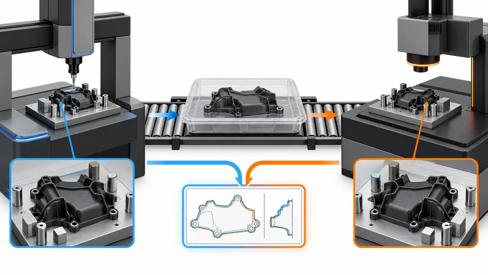
A supplier CMM may report a housing inside tolerance while the customer optical system reports the same feature outside. Averaging the numbers or accepting the favorable lab does not resolve whether the difference comes from the parts, temperature, restraint, datum construction, point selection or software.
Pause disposition and run a controlled correlation on the same identified parts. Align drawing revision, conditioning, measurement timing, environment, fixture forces, datum simulation, program, filtering and reporting. Compare original readings and uncertainty before deciding which method—or revised method—controls acceptance.
Freeze the parts and requirement being compared
Two reports may concern different cavities, lots, conditioning states or drawing revisions even when the characteristic number matches.
Select a stable set of individually identified traveling parts, freeze the requirement and record cavity, lot, molding time, conditioning, prior assembly and handling. Measure the same items in both labs.
Do not compare two population averages as the first correlation experiment. Use enough parts to span expected geometry without intentionally selecting only good or bad pieces. Preserve orientation and protect flexible parts from storage deformation. Confirm units, tolerance, material condition and whether the drawing defines free or restrained state. Record elapsed time because post-mold shrinkage or moisture uptake can change dimensions. Photograph any damage before transfer.
Build the review around traveling-part list, traceability, drawing/revision, conditioning and measurement sequence. Keep the part number, drawing revision, material condition, lot or cavity identity, equipment state and observation method beside the result. The decision is whether both laboratories measure the same stable objects against the same controlled requirement. A result from a different geometry, resin grade, production cell or conditioning state can be useful background, but it is not automatically transferable. Record the mismatch and decide whether a controlled comparison is required. More parts reveal range-dependent bias, while a small well-controlled set is faster for identifying obvious setup differences. Set a named owner and an evidence-based closure condition before the next irreversible commitment.
Align environment and part state
Plastic dimensions can change with temperature, moisture, time and restraint between laboratories.
Agree stabilization time, temperature and humidity recording, moisture/conditioning state, support and measurement timing. If the program requires different conditions, calculate or test their effect rather than ignoring it.
NIST notes the dimensional reference-temperature concept and the need to control environmental effects. NIST’s Engineering Metrology Toolbox FAQ covers calibrations, recalibration intervals and traceability: NIST Engineering Metrology Toolbox FAQ. The applicable drawing or customer procedure governs the part. For nylon, dry and conditioned states cannot be pooled. A warm part measured soon after molding may continue moving. Flexible parts can creep in packaging. Record actual part and room conditions, not only nominal lab setpoints. If thermal expansion correction is used, identify coefficient, reference and uncertainty.
The working record should contain part and room temperatures, humidity/conditioning, stabilization time, storage orientation and any correction method rather than a conclusion copied into email. Review the source, revision, units, sample selection and boundary conditions, then test whether environmental and time effects are matched or explicitly quantified. Preserve failed or marginal observations as well as passing ones; otherwise the team cannot see where the recommendation stops being reliable. Long stabilization improves comparability but may not represent line-side inspection; separate release and correlation methods if both are needed. Translate the accepted condition into the drawing, purchase specification, setup sheet, inspection instruction or change record that production will actually use.
Make datum simulation and fixturing equivalent
The same datum labels can be physically realized with different pins, planes, clamp forces and contact sequences.
Compare fixture drawings, datum target sizes/locations, material modifiers, order of constraint, clamp force and supports. Run a common fixture or reciprocal measurements where practical.
A soft housing may conform to a three-point nest, vacuum fixture or perimeter clamp differently. A pin at maximum material boundary and a best-fit cylinder do not realize the same datum. Inspect fixture wear and calibration and check whether burrs or flash affect seating. Use pressure film, indicators or repeated seating studies when clamp distortion is suspected. Document how the part is loaded and whether the operator can choose contact points.
Ask the supplier to connect fixture CAD, datum simulation, contact and clamp scheme, wear/calibration and repeated seating results to the proposed part and production state. The evidence is sufficient only when both methods establish the part coordinate system without materially different restraint. If inspection cannot observe the mechanism directly, identify the proxy being used and how it was correlated. Do not average incompatible results or hide a trend by pooling cavities, lots, left/right versions or process stages. A common fixture improves method agreement, but it can also transfer one lab’s bias; independent reciprocal checks reveal that risk. Define what change would invalidate the conclusion and route that trigger through normal change control.
Compare point strategy and computation
CMM, scanner and optical systems may sample different areas and apply different filters or best-fit algorithms.
Export original points or feature data where possible and compare point count, distribution, exclusions, probe/stylus, scan direction, filter, outlier rule and fitting algorithm. Which method to use in the first place — CMM, optical scanning or functional gauges — is compared in the measurement-methods guide: CMM, Optical Scanning and Functional Gauges for Plastic Parts.
A drafted or out-of-round hole gives different diameters at different depths. Least-squares, maximum-inscribed and two-point size answer different questions. NIST provides algorithm testing for fitted elemental geometry, illustrating that software computation is part of the measurement chain. NIST’s Algorithm Testing and Evaluation Program for Coordinate Measuring Systems (ATEP-CMS) compares fitting software against reference fits: NIST ATEP-CMS. Confirm whether CAD alignment or drawing datums control. Do not manually delete unfavorable points without a documented rule. For optical edges, lighting, threshold and surface color can shift detection.
Use measurement program, point cloud or original readings, probe/optics, feature construction, filters and algorithm settings to challenge the preferred option. Confirm who produced the record, what population it represents, and whether the current acceptance method could miss the relevant failure. The release test is whether reported values arise from equivalent feature definitions and transparent computation. Dense scanning exposes form but can amplify surface texture and filtering choices; sparse points are efficient yet may miss the functional extreme. Where evidence remains incomplete, authorize only bounded work at risk, with a quantity or activity limit, responsible owner and follow-up record. Commercial urgency does not turn an assumption into product approval.
Assess repeatability, bias and uncertainty
Perfect correlation coefficient can coexist with a constant or size-dependent bias that changes conformity decisions.
Repeat measurements and reseating in each lab, compare paired differences by part, inspect constant and range-dependent bias, and include relevant uncertainty before setting correction or guard bands.
NIST interlaboratory work treats comparison design and uncertainty as essential. The statistical method for linking key-comparison results and computing degrees of equivalence is described in this NIST methodology paper: Linking Results of CIPM and RMO Key Comparisons. Plot lab A minus lab B against part magnitude and cavity or condition. Separate within-lab repeatability from between-lab difference. Investigate step changes by fixture position or operator. Do not average results from incompatible methods. If a correction is considered, verify it on independent parts and define its valid range. Customer rules govern conformity near tolerance limits.
Before closing this point, reconcile paired results, repeat/reseat data, difference plots, uncertainty contributions and independent confirmation set with the controlled product definition. The reviewer should be able to show that the team understands whether disagreement is random, constant, range-dependent or condition-specific. Check at least one credible boundary condition when the mechanism is sensitive to temperature, time, load, moisture, orientation or machine response. A statistical correction can align results within a range, while a physical method correction is preferable when a clear cause can be removed. Keep superseded data and mark the cut-in point of any correction so later complaints or deviations can be contained to the right population.
Release one controlled measurement method
Correlation closes only when drawing interpretation, method ownership and product disposition are clear.
Document the agreed method, program and fixture revisions, correlation result, transition date, affected inventory and authority. How the correlation evidence travels with a shipment — declaration vs measured results — is specified in the shipment-evidence guide: Certificate of Conformance vs. Measured Inspection Results for Automotive Parts. Update control and submission records and monitor for recurrence.
If both methods remain for different stages, define their purposes and decision hierarchy. Re-measure held product only after the method is controlled; do not cherry-pick a lab. Preserve old reports and the rationale for any invalidation. Train operators and protect programs from uncontrolled edits. Use a check artifact or retained parts to verify continuing agreement at a defined interval. A laboratory accreditation scope supports competence but does not itself prove two part-specific methods agree.
Release from this stage should cite approved correlation report, method/fixture revisions, inventory disposition, training and ongoing check plan and explain why future conformity decisions use one authorized and reproducible method or a defined relationship between methods. A polished report is not enough if it omits original readings, specimen state, cavity identity, units or the applicable requirement. Standardizing one method reduces ambiguity, but local production may still need a faster proxy that is demonstrably correlated. Close the loop by defining the ongoing check, reaction threshold and escalation route. The purpose is not extra paperwork; it is to keep the validated condition recognizable when production, demand or supply circumstances change.
Two-lab correlation worksheet
Use paired rows for the same identified parts and preserve original data.
| Review line | Input or evidence | Decision or action |
|---|---|---|
| Requirement | Drawing, feature construction, units and part state | Freeze interpretation |
| Samples | Same IDs, cavities, lots and sequence | Remove population difference |
| Environment | Temperature, humidity, timing and conditioning | Control part state |
| Fixture/datums | Contacts, constraints, clamp and seating | Align coordinate realization |
| Program | Points, depth, filter, algorithm and exclusions | Align computation |
| Decision | Paired bias, uncertainty, method release and inventory | Close disposition |
Resolve simple definition differences before running large studies. A carefully designed small comparison often reveals a datum or section mismatch that more data would merely repeat.
Correlation-study record — numeric fields to complete
Fill in every field from the actual study. A blank field means the correlation is not yet evidence.
| Field | Record | Rule |
|---|---|---|
| Traveling parts (n) | [ ] identified parts, cavities: [ ] , lots: [ ] | Same parts in both labs; do not compare two population averages first |
| Drawing and requirement | Drawing rev. [ ], feature [ ], tolerance [ ] mm, free / restrained state [ ] | Freeze the interpretation before measuring |
| Conditioning | Stabilization [ ] h at [ ] °C / [ ] % RH; elapsed time since molding [ ] | Record actual part and room conditions, not nominal lab setpoints |
| Paired difference per part | Lab A − Lab B for each part: ___ mm (list all, do not average first) | Plot difference against part magnitude and cavity to separate constant bias from range-dependent bias |
| Within-lab repeatability | Lab A [ ] mm, Lab B [ ] mm (repeat + reseat) | Separate within-lab repeatability from between-lab difference |
| Combined expanded uncertainty (U) | U = ___ mm (state coverage factor k and contributors) | Include fixture, temperature, probe/optics and software contributions |
| Normalized error | En = (xA − xB) / √(UA² + UB²) = ___ | Accept the two methods as agreeing when |En| ≤ 1 for the paired comparison; investigate when |En| > 1. En is the standard normalized-error statistic used in interlaboratory comparisons — the rule, not a value, is what is given here |
| Guard band | Acceptance zone = tolerance − U = ___ mm | ISO 14253-1 decision rule: a result inside the guard band is a pass, outside the tolerance is a fail, and between the two is "cannot decide" — state which rule the customer applies before disposition |
| Bias type | Constant / range-dependent / condition-specific: ___ | A statistical correction can align results within a range; a physical method correction is preferable when a clear cause can be removed |
| Method released | Agreed method rev. [ ], fixture rev. [ ], transition date [ ] | Re-measure held product only after the method is controlled; do not cherry-pick a lab |
Boundary: inter-lab correlation is not Gage R&R and not CMM calibration (ISO 10360). Gage R&R asks whether one measurement system repeats; calibration asks whether one machine is true; correlation asks whether two labs measuring the same parts agree — different questions, different evidence.
Applying the method to a defined situation
The supplier measures a drafted bore by probing one circle near the opening; the customer scanner constructs a least-squares cylinder over most of the depth. The same five cavity-identified parts travel between labs after common conditioning. Programs and point data show that depth and feature construction—not part change—create the offset. The drawing is clarified with a measurement section, both methods are revised, and an independent set confirms agreement before held product is re-evaluated.
The conclusion in this situation depends on the stated inputs. Change the material, geometry, load, equipment, quantity, environment or customer requirement and the review must be reopened at the affected line. The value of the exercise is the visible path from input to decision, not the use of a convenient universal number.
Turn the worked review into a short decision record before the team acts. Identify the exact part family and revision, the decision owner, the supplier input date and the next commitment that would become expensive to reverse. Under “Freeze the parts and requirement being compared,” record the starting condition and the evidence that is already controlled. Under “Compare point strategy and computation,” identify the most credible alternative and the consequence of accepting it. Under “Release one controlled measurement method,” state the release condition and the event that would reopen the decision. The first review lines to complete are Requirement, Samples, Environment. Do not mark a line closed merely because a document was received; record whether its revision, sample population, units and boundary conditions match the program being discussed.
Questions for the supplier review
- Are the exact same parts and requirement being compared?
- Do temperature, moisture state and elapsed time match?
- How does each fixture realize and restrain the datums?
- Which points, depths, filters and fitting algorithms create the value?
- What repeatability, paired bias and uncertainty remain?
- Who authorizes the final method and held-product disposition?
A useful response identifies the controlled source, explains assumptions and exceptions, and names the record that will close the issue. Ask for original evidence where the decision is material; a yes/no answer without part, process and revision context is not enough for tooling or production release.
Information to submit for a project-specific review
Provide both reports and original readings, drawing/CAD revision, identified traveling parts, conditioning history, fixtures and programs, lab environments, probe/optical details and conformity decision rules. Use the AutoMoldingPro request form to keep the current drawing, STEP file, material requirement, annual volume, order pattern and validation scope tied to one inquiry. Mark unresolved points as assumptions so they can be priced and closed before tooling or production commitment.
Conclusion
Correlate the complete measurement process, not only the final numbers. Same parts, state, datums, programs and paired evidence allow the team to correct the method and make a defensible product decision.