
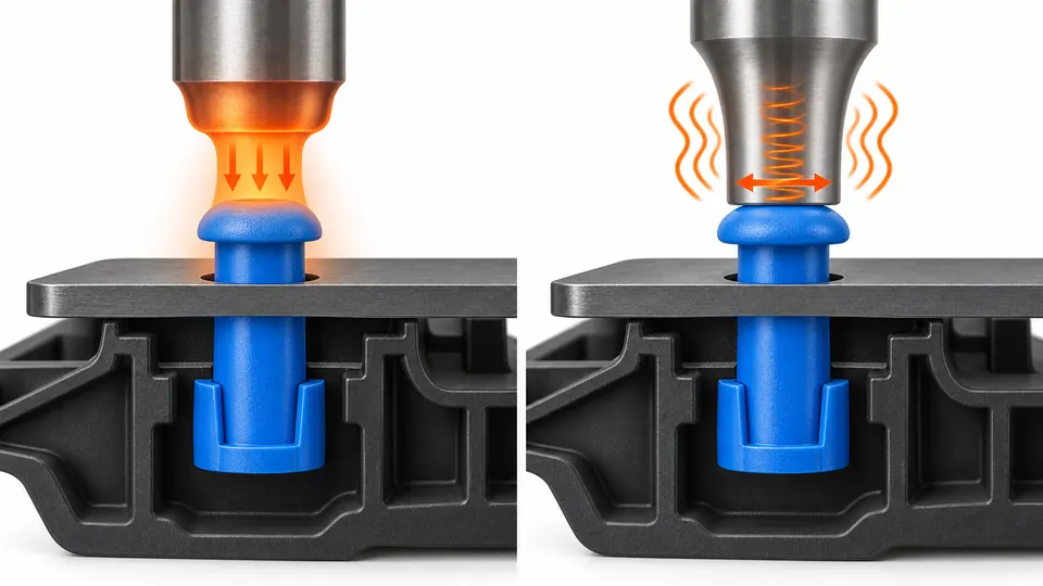
Heat and ultrasonic staking can both reform a molded plastic stud into a retaining head, yet they deliver energy differently. A choice based only on advertised cycle time can damage a cosmetic face, stress electronics, cold-form the boss or produce a head that looks complete but lacks controlled engagement.
Define the retained component, boss and head geometry, resin, required clamp or retention, appearance, nearby sensitive parts and production rate. Compare thermal conduction with localized ultrasonic vibration through trials using representative assemblies. Select the process whose energy path and controls produce verified head geometry and joint function.
Define the joint rather than the machine
Staking captures a component mechanically; it is not automatically a sealed or structural plastic weld.
Specify retained materials and thickness, hole clearance, boss geometry, final head profile, allowed gap, movement and service load. State whether the joint is permanent and what failure mode is acceptable.
The stud must contain enough plastic volume to form the head without starving the root. The retained plate or PCB needs clearance for assembly tolerance while preventing excessive lateral movement. Define support beneath the boss so forming force does not bend the housing. Separate head appearance from retention and clamp. If sealing, electrical spacing or serviceability is required, address it explicitly; a visually smooth head does not prove those functions. When the joint must be removable or serviceable, compare staking with threaded inserts and screws: Thread-Forming Screws vs. Metal Inserts for Automotive Plastic Parts.
Build the review around assembly stack, boss/head drawing, support, gap and movement limits, loads and service requirements. Keep the part number, drawing revision, material condition, lot or cavity identity, equipment state and observation method beside the result. The decision is whether both candidate processes are evaluated against the same defined mechanical joint. A result from a different geometry, resin grade, production cell or conditioning state can be useful background, but it is not automatically transferable. Record the mismatch and decide whether a controlled comparison is required. A larger head can increase capture area but needs more heat/energy, space and cooling and may create sink at the boss root. Set a named owner and an evidence-based closure condition before the next irreversible commitment.
Compare how energy reaches the boss
Heat staking conducts thermal energy from a tip or air; ultrasonic staking converts vibration into localized heating under force.
Map the energy and force path through the stud, retained component and fixture. Identify nearby optics, electronics, coatings, foam and cosmetic surfaces that could be affected.
A heated tip must soften sufficient material and hold pressure while the head solidifies; temperature, dwell and release affect sticking and stringing. Ultrasonic staking depends on horn contact, amplitude/energy and the assembly’s ability to transmit vibration. Filled, soft or damping materials may respond differently. Equipment supplier claims are starting points. Trial the exact resin, color and geometry and monitor coupled damage such as microcracks, particulate, witness or component movement.
The working record should contain energy/force path, material response, sensitive-component map and representative trial observations rather than a conclusion copied into email. Review the source, revision, units, sample selection and boundary conditions, then test whether the chosen process concentrates energy at the stud without unacceptable effects elsewhere. Preserve failed or marginal observations as well as passing ones; otherwise the team cannot see where the recommendation stops being reliable. Ultrasonics can be fast and localized; thermal methods can be more forgiving for dissimilar stacks but add heat and cooling time. Translate the accepted condition into the drawing, purchase specification, setup sheet, inspection instruction or change record that production will actually use.
Design the boss and head for forming
A molding-friendly boss may not contain the volume or access needed for a repeatable formed head.
Size the stud and final head together, provide root radius and support, allow tool approach and vent/clearance, and avoid cold forming. Confirm draft and molding variation in the preform.
Head styles such as dome, rosette or flush profiles distribute material differently. The tool contour should capture the intended volume without cutting the head. The GE design guide describes maintaining pressure during resolidification and avoiding cold forming. Check boss height and diameter by cavity because variation changes head fill. Keep the stud away from a cosmetic wall if heat or force can read through. If multiple stakes share one tool, stack variation and coplanarity matter.
Ask the supplier to connect preform and final-head volume, tool profile, cavity dimensions, backing support and access/coplanarity study to the proposed part and production state. The evidence is sufficient only when the molded stud and forming tool can create the specified head across tolerance. If inspection cannot observe the mechanism directly, identify the proxy being used and how it was correlated. Do not average incompatible results or hide a trend by pooling cavities, lots, left/right versions or process stages. A tall narrow stud is easy to access but may buckle; a short broad stud needs more energy and can build a heavy molded section. Define what change would invalidate the conclusion and route that trigger through normal change control.
Design fixture and equipment around the assembly
Joint consistency depends on nest support, component seating, tool alignment and machine feedback as much as nominal settings.
Locate from stable datums, support each boss reaction path, verify component presence and seating, control tool alignment and define machine capacity for all stakes in the cycle.
A warped housing or variable metal stamping can leave one boss unloaded in a multi-head tool. Measure nest and head parallelism and provide compliant tooling only where controlled. Ultrasonic systems need matched horn/tooling and a stable stack; thermal systems need balanced heater response and tip condition. Protect electronics from fixture pressure and vibration. Define loading orientation and error-proofing. Evaluate manual versus automated handling using actual volume and inspection needs.
Use fixture drawing, support map, component-presence control, head alignment and equipment capacity/feedback to challenge the preferred option. Confirm who produced the record, what population it represents, and whether the current acceptance method could miss the relevant failure. The release test is whether the production cell presents and supports every stud consistently during forming and cooling. Multi-head processing improves takt but couples stack variation and maintenance; sequential heads can adapt individually at longer cycle. How staking and other secondary operations enter the piece-price ledger is covered in the secondary-operations cost guide: Secondary Operations for Automotive Molded Parts: Costs. Where evidence remains incomplete, authorize only bounded work at risk, with a quantity or activity limit, responsible owner and follow-up record. Commercial urgency does not turn an assumption into product approval.
Select process signals that predict joint quality
Temperature setpoint or ultrasonic energy alone may not detect missing components, collapsed bosses or tool wear.
Correlate candidate signals—force, displacement, time, temperature, energy, power or final position—with head geometry and joint tests. Set limits only from representative evidence.
Record full cycles during development and preserve rejected assemblies. A displacement endpoint may detect missing material; force versus position can reveal premature contact; energy can change with material and stack. Thermal tip temperature does not equal polymer interface temperature. Use vision or dimensional checks for head diameter, height, cracks and incomplete flow where they add detection. Challenge sensors with known defects. Define tool cleaning and replacement because residue or horn/tip wear changes response.
Before closing this point, reconcile process traces, head measurements, known-defect challenges, tool condition and correlation with joint performance with the controlled product definition. The reviewer should be able to show that routine monitoring detects the failure modes shown to matter for the selected process. Check at least one credible boundary condition when the mechanism is sensitive to temperature, time, load, moisture, orientation or machine response. Many signals can create false alarms; use the smallest set that has demonstrated detection and a clear reaction. Keep superseded data and mark the cut-in point of any correction so later complaints or deviations can be contained to the right population.
Validate the complete assembled joint
A head can pass initial pull and later relax, crack or damage a retained component after environment and vibration.
Test dimensional/head quality, retention or functional load, section or failure mode, and required environmental/vibration conditions using production-representative assemblies. Define destructive and routine checks.
Use the actual resin condition, retained component, cavity and process. Measure gap and component movement as well as ultimate force where function needs it. Section selected heads to inspect flow and cracks, recognizing that sectioning samples only one plane. After thermal cycling or humidity, repeat critical tests. For electronics, include functional checks before and after staking and exposure. Separate normal assembly acceptance from destructive margin tests. Follow the customer validation and change process; neither method is automatically automotive-approved.
Release from this stage should cite representative joint samples, dimensional and destructive results, environmental/functional checks and defined failure modes and explain why the selected staking process meets joint and component requirements through the required conditions. A polished report is not enough if it omits original readings, specimen state, cavity identity, units or the applicable requirement. Destructive tests provide mechanism evidence but consume parts; correlated process monitoring can support routine control after validation. Close the loop by defining the ongoing check, reaction threshold and escalation route. The purpose is not extra paperwork; it is to keep the validated condition recognizable when production, demand or supply circumstances change.
Staking-process comparison matrix
Compare the two processes using the same assembly stack and acceptance.
| Review line | Input or evidence | Decision or action |
|---|---|---|
| Joint | Stack, stud/head, gap and load | Define common target |
| Energy | Heat path or vibration path and sensitive components | Screen process risk |
| Tooling | Tip/horn, access, support and multi-head variation | Confirm feasibility |
| Material | Exact resin, fill and conditioning | Run representative trials |
| Signals | Force, displacement, energy, temperature and vision | Correlate detection |
| Validation | Head, retention, function and environment | Release process |
The fastest laboratory cycle is not necessarily the best production choice. Include loading, seating, cooling, inspection, tool cleaning and rejected-part handling in takt and cost.
Staking process-selection sheet — thresholds to ask the supplier for
No values are given here, because thresholds depend on the exact boss, resin and retained component. The sheet states what to ask the supplier to state — not what the answer should be. A supplier who cannot state these numbers has not validated the process.
| Decision input | Ask the supplier to state | Why it decides the process |
|---|---|---|
| Head geometry | Minimum head diameter as a multiple of stud diameter: [ ] ; head height range: [ ] mm | A head that looks complete but lacks controlled engagement is not retention |
| Retention | Pull-off / retention force target: [ ] N (from the drawing); test method: [ ] | Force, not appearance, is the acceptance criterion |
| Head variation | Maximum head-height variation across cavities: ___ mm | Cavity variation changes head fill; check boss height and diameter by cavity |
| Sensitive components | Vibration / heat transmitted to the nearest sensitive component: ___ (measured result) | Ultrasonics can damage electronics and optics; heat can read through to a cosmetic face |
| Cycle | Total cycle including loading, seating, cooling and inspection: ___ s | Laboratory staking time is not production takt |
| Monitoring | Process signal that detects a known bad joint (force / displacement / energy / vision): ___ | Temperature setpoint or ultrasonic energy alone may not detect a missing component or collapsed boss |
| Tool condition | Tip / horn cleaning interval: [ ] cycles; replacement criterion: [ ] | Residue or horn/tip wear changes the process response |
Decision logic (qualitative — no numbers are implied):
- If the retained component is vibration-sensitive (populated PCB, optics, sensor) → trial heat staking first; ultrasonics must prove it does not transmit vibration into the component.
- If takt dominates and no sensitive component sits in the vibration path → trial ultrasonic first, and challenge it with known defects.
- If the resin is heavily filled, soft or damping → heat staking is the safer first trial, because filled and damping materials transmit vibration differently.
- If the joint must be removable or serviceable → staking is the wrong family; compare threaded inserts and screws instead.
Applying the method to a defined situation
A plastic housing retains a populated board with six studs. Ultrasonic staking meets cycle goals but transmits vibration into a sensitive connector and produces occasional particulate; heat staking is slower but allows all six heads to form with a supported multi-head fixture. Trials compare component function, head geometry, gaps and pull after thermal cycling. The chosen process is based on validated assembly performance and total cycle, not a generic statement that one technology is always faster.
The conclusion in this situation depends on the stated inputs. Change the material, geometry, load, equipment, quantity, environment or customer requirement and the review must be reopened at the affected line. The value of the exercise is the visible path from input to decision, not the use of a convenient universal number.
Turn the worked review into a short decision record before the team acts. Identify the exact part family and revision, the decision owner, the supplier input date and the next commitment that would become expensive to reverse. Under “Define the joint rather than the machine,” record the starting condition and the evidence that is already controlled. Under “Design fixture and equipment around the assembly,” identify the most credible alternative and the consequence of accepting it. Under “Validate the complete assembled joint,” state the release condition and the event that would reopen the decision. The first review lines to complete are Joint, Energy, Tooling. Do not mark a line closed merely because a document was received; record whether its revision, sample population, units and boundary conditions match the program being discussed.
Questions for the supplier review
- What mechanical function must the formed head provide?
- Does the molded stud contain the required head volume?
- Where do heat, vibration and force travel through the assembly?
- How are all boss locations supported and seated?
- Which process signals detect known bad joints?
- What post-environment joint and component tests release production?
A useful response identifies the controlled source, explains assumptions and exceptions, and names the record that will close the issue. Ask for original evidence where the decision is material; a yes/no answer without part, process and revision context is not enough for tooling or production release.
Information to submit for a project-specific review
Provide assembly CAD, resin and component materials, stud and target head geometry, stack tolerances, retention/gap criteria, sensitive components, volume/takt and environmental validation requirements. Use the AutoMoldingPro request form to keep the current drawing, STEP file, material requirement, annual volume, order pattern and validation scope tied to one inquiry. Mark unresolved points as assumptions so they can be priced and closed before tooling or production commitment.
Conclusion
Select staking from the joint, material, energy path, fixture and evidence. Heat and ultrasonics can both work; the production decision belongs to the exact assembly and correlated controls.
References
- GE Plastics design guide — staking
- Eastman, Keys to successful molding (SP-MBS-1971BF) — general processing and mold design guidelines (not staking-specific).
- Herrmann ultrasonic staking overview