
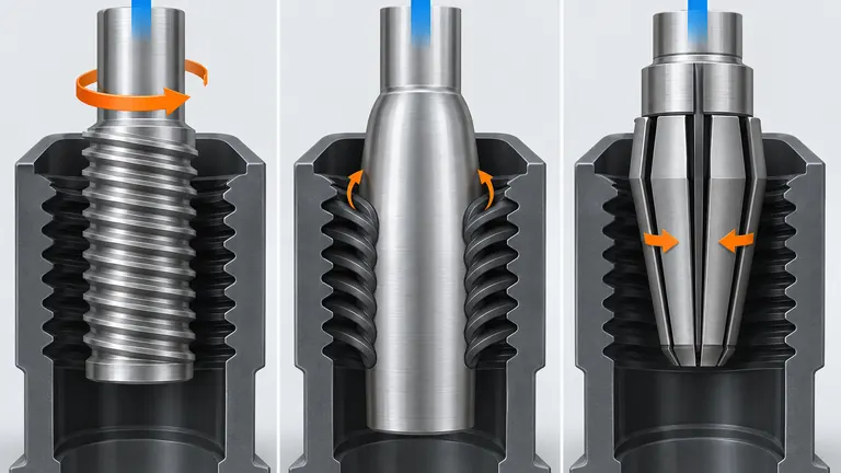
Conceptual illustration; not to scale.
Plastic threads can lock a part onto a core even when the rest of the geometry ejects easily. If the release method is chosen after the thread is designed, the mold may need more space, more motion or more maintenance than the program allows. A thread that looks standard in CAD can also distort, shear or stick when resin behavior and ejection direction are ignored.
Choose the release method from the thread geometry, molded-resin deformation capability, release force, number of starts, undercut depth, part access, anti-rotation needs, cycle target, available mold space and maintenance capability. Unscrewing suits threads that must disengage by rotation; stripping can suit resilient plastic threads with controlled draft and limited undercut; collapsible cores can release selected internal threads or undercuts by reducing the core diameter. Validate the actual thread with a mating component and a defined torque or fit method.
The focus is the plastic thread and its mold mechanism. Metal inserts are mentioned only as a fallback when a molded thread cannot meet the function or release constraints.
Define the thread function before choosing the mechanism
Why this matters: The mechanism cannot be selected from the word “thread” alone. A protective cap thread, a fastener thread, a sensor-retainer thread and a fluid-fitting thread can have different requirements for engagement, torque, sealing, cycle, appearance and repeatability.
Collect the thread model and the mating part. Record major and minor diameter, pitch, lead, start count, thread length, flank form, crest/root radii, truncation, interruptions, reliefs, lead-in, end condition and any non-standard geometry. Identify whether the thread is internal or external, continuous or interrupted, and whether the mating component is metal, plastic, coated or flexible. A standard nominal designation does not replace the actual model and customer specification.
Then define the failure mode. Is the part difficult to remove from the core? Does the thread strip during assembly? Does the mating component cross-thread? Is the required torque stable? Does the thread need to locate, retain, seal or only prevent a cover from falling off? A thread that carries load may need a different material, flank or validation plan from a cosmetic closure.
Release direction and anti-rotation are equally important. Stripping a thread requires enough elastic deformation and a path that avoids damaging the crest. Unscrewing requires controlled rotation and a way to prevent the part from rotating with the core. A collapsible core requires sufficient collapse for the actual undercut and a sequence that returns the segments safely before mold closure.
Use the resin supplier’s data and actual part trials. Modulus, elongation, shrinkage, reinforcement, temperature and moisture condition influence stripping force and thread fit. Filled materials may have less useful deformation in the thread and more wear on the tool. Do not copy a release method from an unfilled cap to a reinforced automotive housing without a design and trial review.
Also define how the thread is verified after molding. A simple pass/fail mating check may be enough for a protective cover, while a load-bearing or serviceable thread may need torque, axial retention or repeated assembly evidence. Record the mating component material and revision. If moisture, temperature or reinforcement changes the fit, specify the state. The release method should be selected only after the product owner explains which of these outcomes is critical.
Use an unscrewing core when rotation is the clean release path
Why this matters: An unscrewing mechanism disengages the molded thread by rotating the core or nut relative to the part. It is suitable when the thread is continuous, the undercut is substantial, the resin should not be forced over the thread, or the assembly function requires a controlled, repeatable thread form.
The mold must provide rotation, axial travel, timing and reaction. Depending on the design, the core can be driven by a hydraulic motor, electric motor, rack-and-pinion, geared mechanism or mold-opening motion. The part must be held against rotation or the thread will not disengage relative to the plastic. That holding function may come from a stripper, external feature, cavity friction or an anti-rotation detail, each with its own risk.
Calculate the required disengagement travel from thread pitch and the number of turns, then check mold opening, ejector or stripper movement, drive torque, acceleration, lubrication and safe return. The thread may require a lead-in and a runout to avoid a sharp end condition. The mechanism also needs access for cleaning and inspection. A powered system can protect a delicate thread but adds controls, seals, sensors and maintenance.
Check cooling around the rotating core. A core that is difficult to cool can lengthen the cycle or produce thread distortion. Check runout and alignment because radial error can change the mating fit or create uneven flank contact. For multi-cavity tools, synchronize or independently manage the threaded mechanisms as the tool design requires.
Ask for evidence from the actual material and thread: release torque, mating torque, strip or cross-thread observation, cycle timing, cavity balance and wear inspection. A thread profile measurement may be useful, but a profile that passes a gage can still fail assembly if the part is oval or the material state changes. Link the result to a functional check and controlled sample condition.
The design review should show the relationship between pitch, rotation, axial travel and part retention. Confirm that the rotating core can be driven and returned without damaging the thread or colliding with the ejector and stripper. Check whether the mechanism stays in the mold or is removed for service. The buyer should ask for drive torque assumptions, sensor or timing confirmation, lubrication, spare parts and a safe recovery method after a cycle interruption. These details often control the real maintenance burden.
Use stripping when the resin and geometry tolerate controlled deformation
Why this matters: Stripping removes the part over a fixed core by elastically deforming the plastic thread or undercut during ejection. It can be simple and compact because it avoids a rotating mechanism, but the part and resin must tolerate the release force without permanent distortion, whitening, cracking or thread damage.
Evaluate the thread’s undercut depth, flank angle, lead-in, core draft, thread length, wall support and distance from flexible features. The part must have a controlled deformation path. A thick, stiff or reinforced thread may not strip reliably, especially at a low ejection temperature. A flexible resin may strip easily but recover slowly or produce a variable mating fit. The actual grade, temperature and molding history matter more than the family name.
The ejection system should distribute force. A stripper plate can support the thread circumference more evenly than a few ejector pins, but it requires accurate alignment and adequate travel. Ejector pins placed near a thin thread can create local marks or distort the part. Draft and surface finish reduce friction, but adding draft may change the functional thread. The moldmaker should show how the part is supported and where the force enters.
Use a development test with the intended thread, resin and process window. Measure release force or torque if the equipment is available, inspect the first and last thread turns, and test a mating component after cooling and any specified conditioning. Check repeated cycles, not just a single successful ejection. A part that releases once may fail when the core temperature, mold temperature or material lot changes.
Stripping is attractive when the cycle needs to stay short and the tool should remain mechanically simple. It becomes risky when the thread carries high assembly torque, has a deep undercut, has little wall support or uses a rigid reinforced resin. If the strip force is near the available margin, consider a collapsible or rotating solution rather than relying on more ejector force.
Do not use ejection pressure as a substitute for a release study. If the part needs more force than the support and resin can tolerate, the result can be a hidden crack or a thread that passes a visual check but fails assembly. Check the first and last turns after ejection and after the part reaches the defined measurement state. A stripper plate, draft change or local relief may improve the margin, but every change should be checked against the thread function and surrounding wall.
Use a collapsible core when radial collapse solves the undercut
Why this matters: A collapsible core uses segments that move radially inward so the molded part can clear an internal thread or undercut. It can be a useful middle path between stripping and a full unscrewing mechanism, but it has geometry limits and sequence requirements that must be checked from the component supplier’s design data.
DME’s collapsible-core guidance describes a sequence in which the center pin withdraws, the core sleeve collapses and a stripper plate ejects the part. It also lists design checks for minor and major diameter, collapse, molded length, depth and face conditions. The available collapse is component-specific; it is not safe to apply a single undercut allowance to every collapsible core.
Provide the core supplier with the actual thread or undercut model, part depth, diameter, collapse requirement, resin shrinkage, draft, cooling needs, ejection sequence and any interrupted thread or cutout. DME notes that standard and mini cores have different capabilities and that some mini-core designs produce interrupted threads rather than a fully continuous thread. That may be acceptable for one retainer and unacceptable for another.
Check the mold sequence carefully. Segment collapse must occur before the part is stripped, and the core must return to molding position before the mold closes. Early ejector return, guided plates, positive stops, lubrication and sensor or mechanical confirmation may be required. A sequence error can damage the core or create a production safety problem.
Consider maintenance. Segments, pins, sleeves, stripper plates and alignment surfaces need cleaning, inspection and spare planning. Glass-filled or abrasive resins may accelerate wear. The core may provide efficient release, but it is not a zero-maintenance insert. Request the supplier’s dimensional limits, setup instructions, serial-number controls, replacement parts and inspection intervals.
The core supplier’s catalog limits should be applied to the actual geometry, not to a nominal diameter selected from a table. Check collapse at the thread location, not only at the tip, and confirm part depth, segment face, shutoff, cooling and center-pin clearance. If the part requires a continuous thread, verify that the selected component does not create interruptions. The mold builder should demonstrate the sequence with a section view and state how a failed return is detected before mold close.
Maintenance planning is part of the choice. Record cleaning access, lubrication, segment inspection, serial-number control, replacement lead time and acceptable wear. A collapsible core can simplify radial release, but it remains a precision mechanism whose condition can affect thread fit and part ejection.
Compare the three options with a project matrix
Why this matters: Use this matrix after the thread function and geometry are defined. The “complexity” column refers to the mold mechanism and its maintenance, not the entire tool.
Use the matrix to eliminate any option that cannot release the actual thread, then compare the remaining options by part risk, mechanism complexity, cycle, space, maintenance and available validation evidence.
| Release option | Best fit conditions | Main risks | Mold complexity | Information to confirm |
|---|---|---|---|---|
| Unscrewing core | Continuous thread, deep undercut, rigid resin, controlled disengagement needed | Rotation timing, anti-rotation, drive wear, cycle and cooling | High; powered or synchronized mechanism | Pitch/lead, turns, travel, torque, holding method, drive, cooling and spares |
| Stripping core | Resilient resin, modest undercut, supported wall, compact/simple tool preferred | Thread distortion, high ejection force, whitening, variable fit | Low to medium | Resin grade, undercut, draft, wall support, ejection force, temperature and functional test |
| Collapsible core | Internal thread or undercut within component collapse and depth limits | Segment wear, sequence error, geometry limits, interrupted-thread restrictions | Medium to high | Core supplier limits, collapse per side, length, diameter, sequence, cooling and maintenance |
| Metal insert fallback | Thread function or durability exceeds practical molded-thread release | Insert cost, loading, retention, thermal mismatch and assembly complexity | Medium to high | Insert material, supply, anti-rotation, pullout/torque, loading and customer approval |
The matrix does not choose a winner by row count. Eliminate options that cannot meet the thread’s geometry or function, then compare cycle, tool space, maintenance and evidence for the remaining options. If a metal insert is being considered, keep the discussion at the fallback level unless the project separately defines insert molding and assembly controls.
Add a row for the project’s unacceptable failure. If cross-threading is unacceptable, a simple pass/fail release check is not enough. If a short cycle is important, include the rotation or collapse time and the time to confirm safe return. If a receiving plant has limited maintenance capability, include training, spares and access. A mechanically simple option can still be the wrong choice if it creates a narrow material or ejection window.
Illustrative example: an interrupted thread is acceptable for a non-sealing retainer, so a collapsible core remains in the comparison. A different part needs a continuous thread and a rigid reinforced resin, so the mini collapsible option is eliminated and stripping is treated as a development risk. The matrix does not reward a mechanism for being familiar; it records why it is compatible with the part and the production environment.
Include an evidence column in the final sourcing decision. For each surviving option, state the test that will prove release, the person who owns it and the point at which the mechanism can be changed without invalidating the product definition. A lower-cost mechanism with no credible functional test is not a lower-risk option. If the tool will be transferred, include the receiving plant’s maintenance and recovery capability; a mechanism that works in the builder’s hands may be unsuitable if the destination lacks the required drive, spare or sequence control.
Validate the thread and release sequence
Why this matters: Validation should cover the molded thread, the mating interface and the mechanism. Define sample state, cavity, resin, process, temperature, conditioning, measurement method and acceptance limits. A thread gage can check form and size; a mating component can check assembly; torque or force testing can check the actual use. Use the combination that represents the function.
Inspect first and last turns, crest damage, flash, ovality, pitch error, flank contact, sink, weld lines and marks. Check whether the part was measured free, supported or assembled. For a thread close to a sealing or retention function, coordinate dimensional and functional evidence rather than approving one in isolation. If the customer requires a particular report or PPAP element, include it in the request and cost scope.
Run the release mechanism across the planned process window. Check cold and warm tools where relevant, startup and steady state, cavity-to-cavity behavior and material-lot changes. A powered unscrewing mechanism should record travel, timing, rotation confirmation and safe return. A stripping core should record ejection force or a controlled proxy and inspect the part after release. A collapsible core should verify collapse, stripper action and full return before close.
Illustrative example: an internal retainer thread is continuous and engages a metal mating component, but the part uses a reinforced nylon grade with limited elastic deformation. Stripping is rejected because the release margin is uncertain. The team compares an unscrewing core with a collapsible core. The collapsible-core supplier confirms that the thread depth and length fit a particular core family but notes a required interruption; the product owner does not accept that interruption. The team therefore selects a rotating core and validates torque, thread form, anti-rotation, cooling and maintenance before production release.
If no release mechanism provides a stable margin, revise the thread geometry, resin or interface, or consider a metal insert with customer approval. Do not hide a mechanism limitation by increasing ejection force or weakening the acceptance test.
The validation record should include the mold mechanism revision, cavity, resin lot, molding conditions, sample state, mating component, measured thread result and release outcome. Repeat the check after a planned maintenance event or component replacement when the customer’s change-control rules require it. If the thread is out, identify whether the cause is geometry, shrinkage, temperature, moisture, mechanism timing, flash or measurement. Correcting the wrong cause can make the next lot less stable.
Conclusion
Define thread geometry, function, resin behavior, release force, space and maintenance before selecting the mechanism. Use unscrewing for controlled rotational disengagement, stripping only with a validated deformation margin, and collapsible cores within their component limits. Confirm the choice with actual mating, torque or force and sequence evidence.
References
- DME, Collapsible Cores Brochure — geometry limits, collapse sequence and design requirements.
- DME, S-Core Premium Collapsible Cores — segment options, undercut release and sequence concepts.
- DME, Collapsible Core Design and Assembly Guide — design checks and mold start-up considerations.
- AutoMoldingPro, Automotive Wire Harness Clip DFM — related published article for retention and functional-fit thinking.