
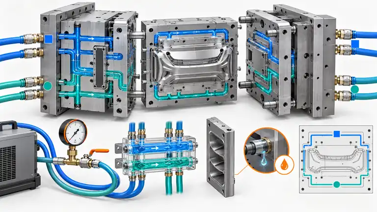
A mold can produce acceptable trial parts yet arrive with crossed hoses, a restricted channel, an undocumented baffle, or a leak that appears only under pressure. The receiving plant then loses time rebuilding a cooling map while dimensions and cycle drift.
Accept cooling circuits as an engineered subsystem. Require a controlled circuit drawing and physical labels, verify routing and connections, test leakage or pressure integrity with an agreed safe method, measure flow and temperature behavior under defined conditions, and preserve clean/dry shipment status. Generic “water passed” evidence is insufficient.
Define the cooling-system deliverables before mold construction
Cooling acceptance is easiest when the required records, interfaces, and test methods are agreed before drilling, assembly, and trial. A late request for a circuit map often produces an inaccurate sketch rather than design-controlled information.
List every thermal-control circuit: cavity, core, inserts, slides, lifters, baffles, bubblers, manifolds, hot-runner plates, hydraulic heat exchangers if relevant, and any circuits requiring separate temperature control. Assign unique circuit IDs and inlet/outlet identifiers. The ID should appear on the mold, drawing, hose map, and setup sheet using the same convention.
Define receiving-plant interfaces: fitting standard and size, connector orientation, maximum hose envelope, supply/return manifold arrangement, water or approved fluid, expected supply temperature range, available pressure and flow, filtration, and corrosion constraints. Export molds often move between plants with different connector conventions; adapters should not create restricted or ambiguous paths.
Require design outputs appropriate to service: plan and section views, bore diameter and length, plugs, baffles/bubblers, series/parallel connections, minimum wall to cavity or other passages, pressure rating basis, flow direction where important, cleaning access, and spare components. Identify blind passages or features that can be installed in the wrong orientation.
Cooling affects more than cycle. Different mold-surface temperatures can change shrinkage, warpage, appearance, ejection, and dimensions. The circuit specification should therefore link to product-critical zones and trial measurement locations. Do not assign one universal flow target across all circuit geometries; the designer should define the performance basis and test condition.
DuPont’s mold-design educational overview treats temperature control and cooling as core mold-design topics alongside gates, vents, ejection, and shrinkage (DuPont mold-design webinar overview). Use material, tool, and equipment suppliers’ detailed requirements for the actual system. The purchase specification should convert those inputs into project-specific deliverables.
Verify circuit identity, continuity, and routing physically
A drawing can be correct while hoses are connected incorrectly or a baffle is assembled backward. Acceptance should trace each physical inlet through its intended return and confirm that circuits are isolated as designed.
Inspect labels first. They should be durable, visible in the installed orientation, and unambiguous after guards or hoses are fitted. Pair inlet and outlet IDs; identify flow direction where required; distinguish water, oil, hydraulic, pneumatic, and hot-runner services. Avoid hand-marked labels that disappear during cleaning or transport.
Use a controlled continuity method suitable for the mold: low-pressure air with safe containment, clean water flow, tracer or another approved technique. Confirm that each inlet exits only at its mapped outlet and that no unintended communication exists between circuits. Observe flow direction through baffles or bubblers where assembly orientation matters. Follow plant safety procedures and component pressure ratings.
| Circuit check | Record | Acceptance question |
|---|---|---|
| Physical identity | Inlet/outlet ID and mold location | Does hardware match the drawing? |
| Continuity | Applied medium and observed return | Is the route open and connected correctly? |
| Isolation | Adjacent ports monitored | Are circuits unintentionally cross-connected? |
| Service access | Plug, baffle, manifold, cleaning access | Can the circuit be maintained? |
| Interface | Fitting, thread, hose clearance | Will it connect to the receiving cell? |
| As-built revision | Changes from original design | Does documentation reflect the delivered mold? |
Record photographs of labels and a completed circuit map. If the tool uses external manifolds, verify internal routing and manifold port identity together. A common “C1 IN/C1 OUT” label is useful only if C1 identifies the exact mold region.
Resolve discrepancies before performance testing. A flow value attached to the wrong circuit has little value. Update the as-built drawing for approved changes rather than annotating a trial worksheet and leaving the design obsolete.
Test leakage and pressure integrity with a defined safe method
“No visible leak” during a short molding trial may miss internal leakage, seepage at static seals, or a weak plug. Define the test medium, pressure, duration, temperature, isolation, and acceptance before the test.
The mold designer and component suppliers should set a safe proof or leak-test pressure within the ratings of hoses, fittings, plugs, seals, manifolds, baffles, and mold components. Do not copy a pressure from another tool or exceed the weakest component. Follow lockout, guarding, pressure-relief, and stored-energy procedures. Water-based testing can reveal external leaks; pneumatic testing stores more energy and needs stricter controls.
Test circuits individually or in defined groups so a failure can be located. Inspect external plugs, fittings, O-rings, slide connections, manifold joints, and parting-line proximity. Monitor pressure decay only with a method that accounts for fluid compressibility, temperature, trapped air, and equipment resolution. A pressure drop is evidence to investigate, not automatically a leak rate.
Check unintended internal communication. Pressurizing one circuit while adjacent circuits are open to observation can reveal cross-leakage. Where water can reach hot-runner electrics, hydraulic systems, or cavity surfaces, define additional safeguards and drying. Husky’s hot-runner service guidance warns that water leakage into a hot runner can damage nozzle heaters and requires water removal before startup (Husky Ultra thermal gate service guidance). Apply the actual system manufacturer’s procedure.
Illustrative example—hypothetical, not an AutoMoldingPro project. A transferred mold has six labeled circuits. Continuity testing shows C4 returns through C5, and pressure testing produces moisture near a buried plug. The team corrects the manifold labels, repairs the plug, repeats isolation and leak checks, and updates the as-built map before running the tool. A successful first shot would not have provided this evidence.
After wet testing, drain, blow out, dry, and protect circuits using approved methods, especially before export storage or freezing exposure. Record the final condition.
Measure flow and thermal performance under reproducible conditions
Flow readings are comparable only when the fluid, temperature, supply pressure, return restriction, valve positions, instrument, and circuit configuration are known. A single number without conditions cannot prove a clean or effective circuit.
Record supply and return pressure, fluid and temperature, flow rate, circuit ID, valve position, instrument identity or calibration status, and test date. Where useful, calculate or trend pressure drop across the circuit. Compare symmetrical or paired circuits and the design expectation, but account for different lengths, diameters, fittings, baffles, and elevation. Equal flow is not automatically required for unlike circuits.
Inspect for restriction and instability. Low flow can result from debris, scale, wrong fittings, collapsed hoses, misoriented baffles, narrow drilled intersections, or excessive series connection. Pulsing or bubbles can indicate trapped air or supply problems. Use flushing or cleaning methods compatible with the mold materials and seals; capture debris rather than pushing it into another circuit.
Then verify thermal behavior during a production-relevant trial. Use the intended temperature-control unit, hose routing, resin, cycle, and mold setup. Allow stabilization and record supply/return temperatures, flow, mold-surface temperatures at defined locations where safe, cycle, and cavity-specific part results. Infrared measurements have emissivity and line-of-sight limitations; contact sensors and thermal imaging should follow a defined method.
HASCO presents comparative cooling-circuit flow testing as a way to evaluate circuit efficiency (HASCO Cooling Tornado technical information). Its product-specific data is not a universal acceptance target. Define project criteria from the mold design, equipment capability, and demonstrated part/process needs.
Approve performance based on both circuit evidence and stable conforming parts—not flow alone.
Package the results for export, receiving, and lifecycle control
Cooling acceptance is incomplete if the data remains in the trial technician’s notebook. The receiving plant needs a usable setup and maintenance record tied to the delivered tool revision.
Assemble an acceptance dossier with the as-built circuit drawing, photographs, ID map, fitting list, component ratings, continuity/isolation results, leak-test method and record, flow/pressure data, trial thermal data, approved hose and manifold setup, cleaning method, water-quality or inhibitor requirement where specified, drainage/drying procedure, and open items. Identify who approved each result and the mold configuration tested.
Before shipment, inspect and record that circuits are drained, dried, protected, capped, and labeled. Do not leave incompatible corrosion inhibitor, standing water, or unrestrained fittings. Package loose manifolds, hoses, plugs, and spares with cross-referenced IDs. Include a receiving checklist.
At the destination, repeat identity, continuity, basic leak, and flow checks before hot startup, especially after transport or storage. Compare results with the source baseline. If flow differs, investigate supply conditions and hose configuration before assuming internal blockage. Re-establish the production thermal condition and verify parts.
For serial maintenance, trend circuit flow or pressure drop where risk justifies it, record cleaning and repairs, and update the map after approved changes. A cooling-circuit change can affect dimensions, appearance, cycle, and process approval; apply the program’s change-control requirements.
For an RFQ or export-mold specification, provide receiving-machine and temperature-control interfaces, resin and cycle objective, critical part zones, fitting standard, water conditions, required test methods, and document format. Ask the toolmaker to return the circuit concept, performance basis, safe ratings, as-built records, test evidence, and shipment preservation. This makes cooling acceptance transferable rather than dependent on the builder’s memory.
Conclusion
Accept mold cooling as a documented subsystem: map and label every circuit, prove continuity and isolation, perform safe leak testing, and measure flow under stated conditions. Verify thermal performance with production-intent parts, then preserve the as-built dossier and dry shipment condition for the receiving plant.