
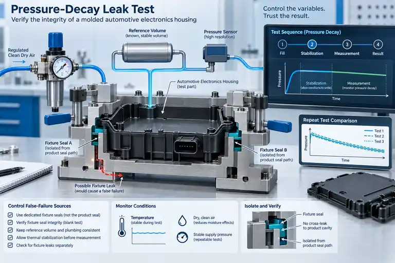
A housing can fail a pressure-decay test because the product leaks, because the fixture leaks, or because temperature and flexible volume changed during the measurement. Repeating the test until a part passes does not distinguish those causes. It can create false rejection, false acceptance and an unstable production limit.
Define the leak path and test medium first, then validate the fixture as part of the measurement system. Control fill pressure, stabilization and measurement time, part temperature, volume, seal contact, clamping and connector blocking. Use master leaks or reference parts appropriate to the equipment, run fixture blank and correlation checks, and investigate repeatability before changing the molded housing or its acceptance limit.
Convert product duty into a test definition
Identify the boundary being tested, normal pressure direction, fluid or gas, operating and environmental condition, allowable leakage or pressure change, and consequence of failure. Decide whether the test is for a bare molding, assembled housing, welded joint, gasketed cover or completed module. Where the boundary is a sensor housing’s cable exit, the sealing architecture that creates that boundary — connector, gland, grommet, backshell, overmold, or potting — and how sealing and strain relief work together at it, is decided in Automotive Sensor Housings: Cable Exit and Sealing Interface Design; this guide does not design the seal, it tests whether the seal as built holds. These are different systems. Air pressure decay can be efficient for production, but its limit needs correlation to the product requirement.
State which ports are open, blocked or connected, what internal components are installed, and whether seals are production intent. A fixture plug that seals on a product surface can bypass the very interface the test is intended to evaluate. Conversely, testing a bare casting-like housing may isolate molding porosity or cracks while saying nothing about the final cover seal.
Design fixture seals that can be challenged separately
Locate fixture seals outside the product leak path where possible and support the housing without distortion. Define seal material, compression, surface contact, replacement interval and clamp sequence. Flexible plastic walls can change internal volume under pressure or clamping; the nest should control position without artificially improving or damaging the product seal.
Provide a way to blank the fixture or use a known-tight reference. Leak-check hoses, valves, couplings and plugs. Monitor wear and contamination at each temporary seal. If the test fails, a fixture-isolation check should determine whether air escaped through product, interface or equipment. Replacing fixture seals on a calendar alone is not enough when damage or contamination can occur between intervals.
Control the test cycle and thermal state
For a basic direct pressure-decay test, fill to the target pressure, isolate the part circuit from the pressure source, allow it to stabilize, then measure the pressure loss. A differential system can include a further reference-isolation step after stabilization; follow the actual circuit and tester manual. The required durations depend on volume, compliance, pressure, equipment resolution and leak limit. Insufficient stabilization can interpret settling or temperature equalization as leakage. Long cycles can improve separation but may not fit production takt, so the test system and product design must be evaluated together.
Use dry, controlled air when applicable and manage part temperature from molding, welding, washing or environmental exposure. A warm part can change pressure as it cools. CTS also explains how temperature and volume differences between master and production parts can shift the reported result. Keep test and reference volumes consistent, record supply pressure and verify that the regulator reaches the intended condition. Do not copy another housing’s stabilization time or conversion factor without correlation.
Pressure-decay parameter worksheet — fill in one row per program
Every value in this worksheet is blank on purpose. No pressure, time, temperature, volume, or allowable-loss value is stated here, because no such value is universal: each one comes from the customer method, the tester manufacturer’s guidance, or a correlation study on the actual part and fixture. Do not copy a value from another housing, another program, or this worksheet’s examples — there are none. A row left blank is an open item, not a default.
| Parameter | How it is set for this program | Agreed value — fill in | Evidence / source |
|---|---|---|---|
| Test pressure, with units | Customer method or product requirement reference | ||
| Test medium and condition (e.g. dry air) | Customer method; tester manual | ||
| Fill time | Trace showing fill complete and stable before isolation | ||
| Stabilization time | Repeated traces at relevant part temperatures and volumes showing settling separated from the measurement interval | ||
| Measurement (test) time | Trace showing the measurement interval starts after settling | ||
| Reference-isolation step (differential systems only) | Tester manual — circuit and valve sequence for this instrument | ||
| Part temperature at test, and how it is controlled | Conditioning record; temperature at test start | ||
| Test volume and reference volume | Fixture drawing; measured volumes for this part and fixture | ||
| Master / known-tight reference part ID | Reference-part record; calibration status | ||
| Known-leak standard, if used, and its certified value | Leak-standard certificate and validity window | ||
| Allowable loss or flow, with units | Product requirement and agreed correlation — not another housing’s limit | ||
| Correlation basis (how the limit traces to the product requirement) | Correlation study on this part, fixture, and boundary | ||
| Fixture blank check — when and how often | Blank-check record; fixture ID and seal state | ||
| Retest rule (whether reclamping is permitted, how many retests, which result controls) | Approved disposition rule; first-failure traces retained |
How to use it: complete the worksheet before the first production test, and re-complete any row a change touches — fixture, program, plug, product interface, or product boundary. A worksheet completed once and never revisited is how an old limit survives a new fixture. The evidence worksheet in "Evidence worksheet for the sourcing or release review" (lines 5–6) is the review checklist for this table; this table is the record of the values themselves.
Separate false failures from real intermittent leaks
First repeat under the defined method without reseating if possible; then inspect the result pattern across time, fixture nests and reference checks. A fail that follows one fixture seal suggests a measurement-system issue. A fail that follows a cavity, weld condition or localized product surface suggests a product or process cause. A pass after rotating or reclamping the part indicates seating sensitivity that itself needs action.
Use controlled diagnostic methods such as fixture blanking, known leak standards, soapy solution where appropriate, tracer methods or subassembly isolation according to safety and product requirements. Preserve failed samples and test logs. Do not raise the limit merely because failures are difficult to locate, and do not modify mold steel until the leak location and mechanism are supported.
Validate the system and maintain comparability
Challenge the equipment with reference conditions around the decision boundary as supported by the tester manufacturer and customer method. Assess repeatability across operators, nests, shifts and relevant temperatures. Confirm calibration and maintenance status, but remember that calibrated pressure sensing does not validate fixture sealing or part loading.
The report should include part and assembly state, revision, cavity or batch, fixture ID, seal state, medium, pressure, cycle times, temperature, result, limit, equipment ID and failure disposition. When a fixture, program, plug or product interface changes, evaluate correlation before mixing old and new data. A production test remains credible only while its physical boundary and measurement behavior remain controlled.
Evidence worksheet for the sourcing or release review
Trace one complete leak-test cycle through the worksheet, including the isolation and stabilization stages. Connect each pressure result to the fixture, temperature condition and calibrated reference used.
| Evidence line | What the reviewer should be able to verify |
|---|---|
| 1. defined product boundary and pressure direction | The test drawing names the bare/assembled boundary, included seals and pressure direction; plugs do not bypass the interface being evaluated. |
| 2. test medium, pressure and acceptance basis | Medium, pressure, units and allowable loss/flow are linked to the product requirement and agreed correlation, not another housing’s limit. |
| 3. part assembly and conditioning state | The tested assembly, seal state, conditioning and temperature match the validation basis, including heat from earlier operations. |
| 4. fixture drawing and temporary-seal locations | Temporary seal contact, compression, clamps and support are defined; the fixture can be challenged without masking a product leak. |
| 5. fill, stabilization and measure sequence | The circuit and valve sequence identify source isolation, stabilization and measurement; timings are verified for this volume and thermal/compliance state. |
| 6. reference, blank and known-leak checks | Known-tight/reference and known-leak checks distinguish equipment loss from product loss and challenge the decision boundary using the tester’s method. |
| 7. repeatability across nests and temperatures | Controlled repeated/crossover tests compare nests at equivalent part temperatures; an apparent nest effect is not confounded with cooling. |
| 8. traceable results and failure localization | Logs retain part/cavity/lot, nest, temperatures, cycle parameters and original failures; localization supports fixture repair or product correction. |
Questions that expose weak assumptions
| Question | A useful supplier answer should include |
|---|---|
| Does the fixture bypass any product seal path? | A section showing each temporary seal relative to the product interfaces, with a check that intended leak paths remain exposed. |
| Can the fixture be tested independently of a part? | A documented blank or known-tight reference arrangement that includes the relevant hoses, valves, couplings and temporary seals. |
| How was stabilization time established? | Repeated traces at relevant part temperatures and volumes showing settling is separated from the measurement interval at the required sensitivity. |
| What temperature and compliance changes affect pressure? | Part and air temperature, flexible-wall movement, clamping and reference/test volume differences, assessed under the actual cycle. |
| Can failed parts be localized without repeated reseating? | Preserved first-failure traces and a controlled isolation/localization sequence; reseating and retesting follow a predefined disposition rule. |
| Which changes require a correlation study? | An impact review for fixture seals, plugs, tubing volume, program/pressure/timing or product-boundary changes before old and new results are combined. |
Illustrative example
A molded electronics cover fails intermittently on one of two test nests. A pass on the other nest after cooling is initially inconclusive because both nest and temperature changed. The team conditions the identified parts to the same defined temperature and repeats a controlled crossover between nests. A blank test then reveals decay at a worn connector plug on the first nest. Replacing the plug restores reference performance, and the matched-temperature comparison confirms the correction. Original failures remain in the record; product disposition follows the approved retest rule.
What to send for a project-specific review
For a leak-test review, send the product boundary drawing, fixture seal layout, tester/circuit, pressure and time settings, part-temperature range, reference checks and first-failure traces through the project RFQ. Identify whether the requirement applies to the bare housing or completed assembly. If the completed assembly is a potted sensor module, the housing features that make the module dispensable — fill access, high-point vents, cure behaviour, and inspection access — are designed in Automotive Sensor Housings for Potting: Fill Access, Air Release and Cure Stress; the leak test defined in this guide then proves the sealing boundary that potting design creates, it does not replace the fill/vent/cure design.
Connect genuine leaks to molding and assembly evidence
After measurement credibility is established, map failures to manufacturing history. Bare housings require review of parting lines, shutoffs, knit lines, inserts and cracks. Assemblies add gasket seating, weld, fastener sequence, connector seal, vent membrane and contamination.
Pressure decay reports system behavior; it generally does not locate the leak. Use a safe diagnostic method and preserve the failed state before disassembly. A fixture leak calls for test maintenance, while a flash-damaged gasket land or failed weld requires a different correction.
Control retests. Repressurization can reseat seals, move debris, alter temperature or enlarge a crack. State whether reclamping is permitted, how many retests are allowed and which result controls disposition. “Test until pass” biases the record.
Challenge relevant temperature, volume and fixture conditions before release, then confirm cycle and maintenance. If product boundaries or limits change, re-establish correlation rather than editing the instrument program alone.
References
- Cincinnati Test Systems — What Is Leak Testing (direct pressure-decay sequence)
- CTS — Differential Pressure Decay Test with Leak Standard Calibration (circuit and calibration)
- CTS — Single-Point Calibration vs. Two-Point (temperature and volume effects in calibration)
- ATEQ — Leak Testing Academy: Methods for Leak & Flow Testing (pressure-decay explanation)