
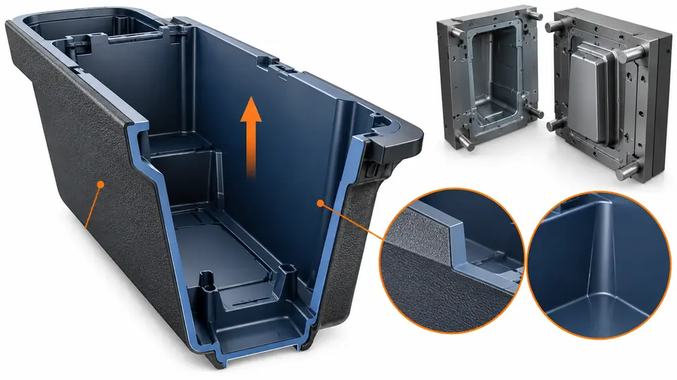
A deep console housing can satisfy the nominal CAD envelope and still scrape its grain, stick to the wrong mold half or distort during ejection. Adding a single draft value after styling is frozen often moves gaps, attachment points and visible walls without resolving the actual draw path.
Define the mold opening direction and part retention first, divide surfaces by depth, texture and visibility, then agree draft with the texture provider and moldmaker for the exact resin and geometry. Protect functional interfaces through datums or local design changes, and validate ejection, grain and installed appearance on representative samples. The cosmetic-acceptance guide defines how grain and gloss are judged on those representative samples.
Map the draw direction before assigning draft
Draft is measured relative to mold movement, so a number has no meaning until the draw direction and parting strategy are fixed.
Run a face-by-face draft analysis from the proposed opening axis. Mark A-side, B-side, shutoffs, side actions, texture zones, deep ribs and surfaces that control vehicle fit.
Worked example — what draft costs on a deep wall. Wall depth and texture depth below are assumed for illustration (not an AutoMoldingPro measurement); the method, not the numbers, is the deliverable. Take a 120 mm deep console wall with a 0.05 mm medium texture. Stratasys’ design guidelines state a general rule of 1.5° of draft per 0.025 mm of texture depth, in addition to the normal draft — so this texture alone calls for 3.0° (0.05 ÷ 0.025 × 1.5). Protolabs’ draft guidance requires a minimum of 3° for a light bead-blast finish (PM-T1) and 5° or more for a medium bead-blast finish (PM-T2). The texture requirement governs, so the wall needs 5°:
Draft Wall growth per side over 120 mm Source of the number 2° 4.19 mm (120 × tan 2°) Illustrative — what a styling-only draft would give 3° 6.29 mm (120 × tan 3°) Stratasys texture rule for 0.05 mm texture; Protolabs PM-T1 minimum 5° 10.50 mm (120 × tan 5°) Protolabs PM-T2 minimum — governs this wall A 5° draft grows each side of the wall by 10.5 mm from the parting line to the base. If the design cannot accept that growth — at a gap, an attachment point or a mating face — the texture, the split line or the wall depth must change; the draft cannot simply be reduced, because the grain will then drag and scrape on ejection. Note that the common 1°-per-inch-of-depth rule alone would suggest about 4.7° for a 120 mm wall (120 ÷ 25.4 ≈ 4.7 in) — close to, but still below, the 5° the texture requires. When depth and texture point different ways, the texture requirement governs.
The housing should remain on the ejection side after opening. Features drafted toward the cosmetic cavity can pull the part in the wrong direction or tear internal tabs. A core-cavity approach may avoid inaccessible deep steel ribs and improve polishing, venting and cooling access. The rib-and-boss guide sets the rib and boss limits that keep those deep ribs from sinking the show surface.
Record what was agreed with the texture provider and moldmaker before steel is cut. One row per texture zone; a blank "draft agreed" cell means the zone is not yet agreed, however far styling has progressed.
| Texture zone | Texture designation and depth | Draft agreed | Grain direction | Master / boundary sample | Repair boundary |
|---|---|---|---|---|---|
| [ ] | [ ] | [ ] | [ ] | [ ] | [ ] |
| [ ] | [ ] | [ ] | [ ] | [ ] | [ ] |
| [ ] | [ ] | [ ] | [ ] | [ ] | [ ] |
Review whether a styling wall can be split across tool halves without an objectionable parting line. Agree parting lines and ejection witnesses alongside the draw direction and visible-surface requirements. Preserve the analysis with the released CAD revision; screenshots without axis and tolerance context are not enough.
Build the review around color-mapped draft analysis, tool opening axis, A/B ownership and parting/shutoff proposal. The decision is whether every molded face has a feasible release direction and the part stays on the intended side. Rotating the draw axis may improve one wall while creating side actions, visible parting lines or difficult attachment geometry elsewhere.
Relate wall depth, shrinkage and resin to draft
Long walls stay in contact with mold steel during more ejection travel and can grip the core as the polymer shrinks.
Evaluate actual wall depth, resin shrinkage and stiffness, wall thickness, cooling and ejection path. Use supplier draft values as starting points only, then agree the project value with the texture source and moldmaker.
Protolabs notes that required draft depends on wall depth, material, finish and manufacturing method. Its published values describe its own service conditions, not an automotive standard. Deep walls with slight bow or local thickness can contact steel even when nominal CAD shows clearance. Filled materials may mark differently from unfilled grades. Check the inside and outside walls together so draft does not create an unintended wedge thickness or move the top opening beyond the package.
The working record should contain wall-depth map, exact resin and shrinkage data, nominal section and ejection-contact review rather than a conclusion copied into email. Review the source, revision, units, sample selection and boundary conditions, then test whether the proposed taper provides release clearance while preserving thickness and assembly envelope. More draft generally helps release, but it changes opening size, visible stance, storage volume and mating gaps.
Convert the appearance specification into texture zones
“Leather grain” or a texture code does not define orientation, depth, gloss, masking boundaries or acceptable repairs.
Obtain the approved texture reference and provider recommendations. Mark grain code, orientation, depth or process, gloss/appearance zone, boundary, no-texture shutoffs and repair approval on controlled data.
Texture creates microscopic undercuts and increases drag on walls parallel to draw. Deep recesses may also be difficult to polish or etch consistently. Grain orientation should follow the customer’s installed-view requirement rather than the moldmaker’s convenience. Identify where texture wraps a radius and where separate tool inserts could leave a witness. Keep critical seals, slides and shutoffs smooth unless the design intentionally allows texture. Color and resin can change perceived grain, so approve appearance on the actual material system.
Ask the supplier to connect approved grain plaque or digital standard, provider draft guidance, zone drawing and installed viewing conditions to the proposed part and production state. The evidence is sufficient only when each textured surface has a controlled reference, direction and feasible release condition. Coarser texture can hide minor flow variation but requires more release allowance and can accentuate sink or mismatch under directional light.
Protect fit while adding necessary taper
Draft can move locator walls, switch openings, trim gaps and attachment interfaces if it is applied from the wrong pivot.
For each dimension affected by taper, define the controlling section and datum. Pivot or offset surfaces intentionally, then recalculate mating clearances and tolerance stacks in installed condition.
A dimension at the top of a deep wall differs from the same nominal value near the base after draft. The drawing should state where size is evaluated. Critical locating features may use short local lands, separate slides or redesigned interfaces, but zero draft should not be accepted without a release strategy. Avoid creating a thin knife edge at the top or a thick mass at the base. Review the counterpart, foam wrap, bezels and fastener access rather than treating the housing alone.
Use before/after envelope comparison, datum sections, mating CAD and tolerance-stack review to challenge the preferred option. The release test is whether added draft does not create an unreviewed change to installed gap, alignment or assembly access. Local slides can preserve near-vertical interfaces but add witness, wear and cost; moving the functional datum may be simpler if the assembly permits it.
Design ejection and steel access with appearance in mind
Deep housings need enough ejection area and accessible tool steel without placing marks on visible zones.
Map ejector pins, sleeves, blades or stripper contact, required stroke, venting and polished access. Keep loads on supported non-cosmetic areas and confirm that the part clears texture before lateral movement.
Ejectors should not push unsupported thin walls or distort clip locations. A large core can develop vacuum; venting and surface finish influence release. Deep ribs and slots may be impossible to polish or texture uniformly with the proposed tool split. Show how slides retract and where their witnesses appear. Review service access for polishing or texture repair because future blending can create visible mismatch. The release sequence should not drag the grain after ejection begins.
Before closing this point, reconcile ejector layout, contact-area calculation, stroke/clearance sequence, venting and tool-access review with the controlled product definition. The reviewer should be able to show that the tool can release the part repeatedly without unacceptable marks, distortion or inaccessible steel. Distributed ejection reduces local stress but creates more witness locations; a stripper system may improve load distribution at greater tool complexity.
Approve samples under repeatable appearance conditions
A textured surface can look acceptable under one lamp and show drag, gloss difference or sink when installed in the vehicle.
Define viewing direction, lighting, distance, angle, clean state and boundary samples. Inspect multiple cavities and time points, then verify dimensions and assembly after ejection has stabilized.
Use the actual resin, color and approved tool texture. Record cavity and process condition; do not use one polished sample to accept a production population. Check grain continuity, drag, scuff, gloss, sink shadow, parting lines and ejector read-through. Compare the housing in the relevant assembly because restraint can alter gaps and surface reflections. If texture is repaired, define the reapproval scope. Cosmetic approval does not replace dimensional or functional release.
Release from this stage should cite approved boundary samples, viewing procedure, cavity/time sample set and installed-condition checks and explain why representative parts meet both release and visible-surface requirements under controlled inspection. Tighter cosmetic screening can increase handling and subjective disagreement; controlled references and inspector alignment improve consistency.
Deep-housing draft and texture review map
Review each surface group rather than applying one global angle.
| Review line | Input or evidence | Decision or action |
|---|---|---|
| Draw | Opening axis, A/B side, slides and shutoffs | Confirm release path |
| Depth/material | Wall travel, resin, shrinkage and stiffness | Set project draft basis |
| Texture | Code, depth, orientation, boundary and provider guidance | Protect grain and release |
| Interfaces | Datum section, mating gap and assembly access | Preserve fit |
| Ejection | Contact, stroke, vacuum, venting and marks | Avoid damage/distortion |
| Approval | Lighting, boundary sample, cavity and installed check | Release appearance and function |
Where one surface cannot satisfy appearance, package and release simultaneously, record alternatives such as moving the parting line, changing texture, adding a side action or revising the mating interface.
Applying the method to a defined situation
A tall console bin has coarse grain on its outside wall and a near-vertical switch opening at the top. Draft analysis shows the part would grip the cavity and the opening shifts beyond its bezel gap if all taper is added from the base. The team changes the core-cavity split, pivots the cosmetic wall from the controlled upper section, leaves a short functional land formed by a local action, and confirms the texture supplier’s draft recommendation. Samples are inspected under the installed lighting direction and checked in the bezel before approval.
This illustrative scenario is not a customer case.
Questions for the supplier review
- Which axis and mold half own every deep surface?
- What exact resin, wall depth and texture process support the draft value?
- Where is each tapered dimension evaluated?
- Can the texture provider reach and repair the proposed steel?
- How does the ejection sequence clear grain before sliding contact?
- What lighting and installed condition control appearance approval?
Information to submit for a project-specific review
Provide released CAD, visible-surface and grain map, resin/color, mating components, gap and datum requirements, tooling concept and appearance acceptance method. Submit these inputs through the AutoMoldingPro request form. Mark unresolved points as assumptions so they can be priced and closed before tooling or production commitment.
Conclusion
Treat draft, texture, draw direction and installed fit as one decision. A face-by-face release map and controlled appearance evidence are safer than adding a generic angle after the housing geometry is fixed.
References
- Protolabs draft angle guidance
- Protolabs mold texture guidance
- Protolabs core and cavity placement
- Stratasys Direct, "Injection Molding Design Guidelines" — 1.5° draft per 0.025 mm texture depth; rib and boss rules: https://www.stratasys.com/siteassets/sdm/resources/design-guidelines/injection-molding/injection_molding_design_guidelines_2017.pdf?v=499c06