
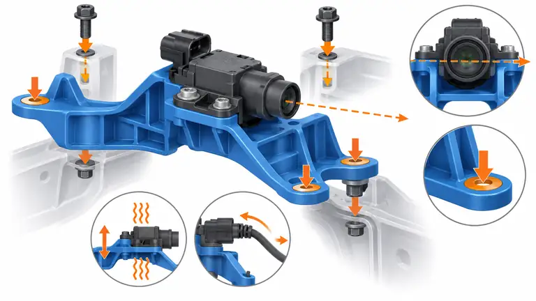
A sensor may be accurate on its bench while its plastic bracket tilts under screw torque, cable force, heat or vehicle vibration. Tightening every molded dimension does not solve a load path that bypasses weak supports or a datum scheme that does not represent installation.
Define the sensor’s required position and allowable movement from functional vehicle references. Carry assembly and service loads through supported plastic geometry, choose accessible datums, and validate the complete mounted system across material and environmental conditions.
The engineering path is functional alignment, vehicle location, load transfer, moldable structure, assembly control and system evidence.
Bracket vs. housing — the boundary. This guide is about the bracket, not the housing. The bracket is the mounting structure: it seats in the vehicle on real pads, holes, slots, pins, or bushings, constrains the sensor’s position against vehicle references, and carries assembly and service loads — fastener torque and clamp, connector insertion, harness pull, vibration, impact, thermal growth, and service handling — through supported plastic geometry into vehicle structure. The housing is the enclosure around the sensor and its electronics: it protects the sensing element, carries the connector and cable interfaces, and seals the cable exit against the environment. A bracket does not seal — sealing is the housing’s job. A housing does not locate the sensor in the vehicle on its own — that is the bracket’s job. If the failure is "the sensor moved, tilted, or lost alignment," start here; if the failure is "water or contamination got in at the cable exit," start with Automotive Sensor Housings: Cable Exit and Sealing Interface Design, the hub for the sensor-housing set, which also points to the housing tolerance pack, the potting design, and the leak test. This guide does not repeat the hub’s content — it owns only the bracket side of the boundary. Where the bracket mounts to a sealed enclosure such as an EV battery pack housing, the enclosure boundary, seal lands and load paths are defined in Injection-Molded EV Battery Pack Housings: Sealing, Flame Rating, Structural Strength and HV Insulation.
Translate sensor function into bracket requirements
field of view, target direction, gap, connector access and allowable static or dynamic movement affects whether the application fits, looks acceptable and remains controllable in production.
Define mapping device-critical axes and surfaces to vehicle references before dimensioning the bracket with the actual assembly and released requirements. Verify the result on representative molded parts rather than treating a design rule as universal.
The review should begin with the physical function rather than a preferred manufacturing answer. The technical focus is field of view, target direction, gap, connector access and allowable static or dynamic movement. Put that focus into the drawing, interface definition, quotation or validation plan that governs the work. Use the exact grade, geometry and condition under review, and identify connected characteristics that may move with the decision.
Use this sequence: mapping device-critical axes and surfaces to vehicle references before dimensioning the bracket. Assign unresolved inputs to named owners, freeze the working revision and state the next commitment that would be costly to reverse. Trials should use representative material, tooling, equipment and handling; a prototype or illustrative comparison must remain clearly identified when it is not production evidence.
The minimum inputs are sensor supplier drawing, vehicle coordinate system, target envelope, angular and positional needs, connector and harness loads, calibration strategy. Check units, conditioning, sample identity and requirement source. Request controlled customer documents instead of guessing proprietary rules. Tighter location can protect calibration but increase tooling and assembly sensitivity; some systems can compensate only within verified limits. Preserve the rejected alternative and its reason because volume, environment, appearance, assembly or equipment changes can reverse the choice.
The main failure path is specifying a tight bracket profile without identifying which direction affects sensing performance. Isolate variables and watch coupled effects on dimensions, appearance, strength, cycle or inspection. Closure requires a functional requirement map connects sensor output or alignment to measurable bracket interfaces. Connect original evidence to part and drawing revision, cavity or fixture, material lot and process state; then record both an acceptance condition and a reaction that tells production when to stop or reopen the review.
Select functional mounting datums
the real pads, holes, slots, pins or bushings that seat the bracket in the vehicle and constrain six degrees of freedom affects whether the application fits, looks acceptable and remains controllable in production.
Define building a datum sequence that mimics assembly and remains accessible to production measurement with the actual assembly and released requirements. Verify the result on representative molded parts rather than treating a design rule as universal.
Treat this as a controlled interface between design intent and production evidence. The technical focus is the real pads, holes, slots, pins or bushings that seat the bracket in the vehicle and constrain six degrees of freedom. Put that focus into the drawing, interface definition, quotation or validation plan that governs the work. Use the exact grade, geometry and condition under review, and identify connected characteristics that may move with the decision.
Use this sequence: building a datum sequence that mimics assembly and remains accessible to production measurement. Assign unresolved inputs to named owners, freeze the working revision and state the next commitment that would be costly to reverse. Trials should use representative material, tooling, equipment and handling; a prototype or illustrative comparison must remain clearly identified when it is not production evidence.
The minimum inputs are vehicle hard-point tolerances, bracket contacts, fastener clearance, slot direction, surface size, draft, flash and fixture access. Check units, conditioning, sample identity and requirement source. Request controlled customer documents instead of guessing proprietary rules. A slot can absorb stack and thermal growth while reducing location in one direction; a round-round pattern locates strongly but may bind. Preserve the rejected alternative and its reason because volume, environment, appearance, assembly or equipment changes can reverse the choice.
The main failure path is using a cosmetic surface as a datum, over-constraining multiple holes or creating tiny unstable contact pads. Isolate variables and watch coupled effects on dimensions, appearance, strength, cycle or inspection. Closure requires datum simulation and correlation show the inspection setup reproduces the installed reference frame. Connect original evidence to part and drawing revision, cavity or fixture, material lot and process state; then record both an acceptance condition and a reaction that tells production when to stop or reopen the review.
Map assembly and service load paths
fastener torque and clamp, connector insertion, harness pull, vibration, impact, thermal growth and service handling affects whether the application fits, looks acceptable and remains controllable in production.
Define drawing each load from its input through bosses, ribs and datums into vehicle structure with the actual assembly and released requirements. Verify the result on representative molded parts rather than treating a design rule as universal.
The useful question is not whether the option can work once, but whether its boundary conditions are visible. The technical focus is fastener torque and clamp, connector insertion, harness pull, vibration, impact, thermal growth and service handling. Put that focus into the drawing, interface definition, quotation or validation plan that governs the work. Use the exact grade, geometry and condition under review, and identify connected characteristics that may move with the decision.
Use this sequence: drawing each load from its input through bosses, ribs and datums into vehicle structure. Assign unresolved inputs to named owners, freeze the working revision and state the next commitment that would be costly to reverse. Trials should use representative material, tooling, equipment and handling; a prototype or illustrative comparison must remain clearly identified when it is not production evidence.
The minimum inputs are hardware, torque and friction assumptions, mating surfaces, cable routing, mass, acceleration or vibration inputs, temperature and service procedure. Check units, conditioning, sample identity and requirement source. Request controlled customer documents instead of guessing proprietary rules. Stiffer ribs reduce movement but can create sink and transmit shock; compliant features protect the sensor while allowing alignment change. Preserve the rejected alternative and its reason because volume, environment, appearance, assembly or equipment changes can reverse the choice.
The main failure path is letting a screw boss carry bending through a thin wall or adding ribs that do not connect to a supported datum. Isolate variables and watch coupled effects on dimensions, appearance, strength, cycle or inspection. Closure requires load calculations or simulation plus physical tests identify stresses, deflection and failure mode at relevant conditions. Connect original evidence to part and drawing revision, cavity or fixture, material lot and process state; then record both an acceptance condition and a reaction that tells production when to stop or reopen the review.
Develop moldable bracket structure
wall, ribs, bosses, fillets, draft, gate, weld line and fiber orientation around loaded and measured features affects whether the application fits, looks acceptable and remains controllable in production.
Define creating continuous load paths with cored sections and reviewing flow and cooling before steel with the actual assembly and released requirements. Verify the result on representative molded parts rather than treating a design rule as universal.
A supplier recommendation becomes actionable only when its assumptions can be checked against the released product. The technical focus is wall, ribs, bosses, fillets, draft, gate, weld line and fiber orientation around loaded and measured features. Put that focus into the drawing, interface definition, quotation or validation plan that governs the work. Use the exact grade, geometry and condition under review, and identify connected characteristics that may move with the decision.
Use this sequence: creating continuous load paths with cored sections and reviewing flow and cooling before steel. Assign unresolved inputs to named owners, freeze the working revision and state the next commitment that would be costly to reverse. Trials should use representative material, tooling, equipment and handling; a prototype or illustrative comparison must remain clearly identified when it is not production evidence.
The minimum inputs are exact resin grade and conditioning, wall map, tool direction, gate concept, weld locations, ejector plan, machine and expected shrinkage. Check units, conditioning, sample identity and requirement source. Request controlled customer documents instead of guessing proprietary rules. Coring reduces sink and cooling mass but can require tool actions; filled materials increase stiffness while introducing orientation and wear effects. Preserve the rejected alternative and its reason because volume, environment, appearance, assembly or equipment changes can reverse the choice.
The main failure path is thickening a boss to gain strength, placing a weld at its root or applying isotropic shrinkage to reinforced material. Isolate variables and watch coupled effects on dimensions, appearance, strength, cycle or inspection. Closure requires DFM, flow review and trial sections demonstrate fill, surface and dimensional stability around critical supports. Connect original evidence to part and drawing revision, cavity or fixture, material lot and process state; then record both an acceptance condition and a reaction that tells production when to stop or reopen the review.
Control assembly without distorting the bracket
how tightening sequence, washer or flange contact and harness connection alter sensor position affects whether the application fits, looks acceptable and remains controllable in production.
Define defining hardware, seating surfaces, torque or angle method, sequence and confirmation checks with the actual assembly and released requirements. Verify the result on representative molded parts rather than treating a design rule as universal.
Separate the mechanism being controlled from the document used to report it. The technical focus is how tightening sequence, washer or flange contact and harness connection alter sensor position. Put that focus into the drawing, interface definition, quotation or validation plan that governs the work. Use the exact grade, geometry and condition under review, and identify connected characteristics that may move with the decision.
Use this sequence: defining hardware, seating surfaces, torque or angle method, sequence and confirmation checks. Assign unresolved inputs to named owners, freeze the working revision and state the next commitment that would be costly to reverse. Trials should use representative material, tooling, equipment and handling; a prototype or illustrative comparison must remain clearly identified when it is not production evidence.
The minimum inputs are fastener grade, head and washer geometry, joint stack, boss compression limit, tools, torque audit, clip/connector forces and access. Check units, conditioning, sample identity and requirement source. Request controlled customer documents instead of guessing proprietary rules. Higher clamp load can resist slip but creep or crush plastic; compression limiters improve control at added part and tooling cost. Preserve the rejected alternative and its reason because volume, environment, appearance, assembly or equipment changes can reverse the choice.
The main failure path is using screw torque to force mismatched datums together or measuring alignment before the final harness load is applied. Isolate variables and watch coupled effects on dimensions, appearance, strength, cycle or inspection. Closure requires mounted measurements before and after assembly operations show position remains within the functional window. Connect original evidence to part and drawing revision, cavity or fixture, material lot and process state; then record both an acceptance condition and a reaction that tells production when to stop or reopen the review.
Validate position and durability as mounted
initial alignment, retention and movement after temperature, vibration, cycling, fluids or service events affects whether the application fits, looks acceptable and remains controllable in production.
Define testing representative molded brackets with production hardware and vehicle-like fixtures in the required sequence with the actual assembly and released requirements. Verify the result on representative molded parts rather than treating a design rule as universal.
Close this point at the level of the specific feature, material state, process step or inspection result. The technical focus is initial alignment, retention and movement after temperature, vibration, cycling, fluids or service events. Put that focus into the drawing, interface definition, quotation or validation plan that governs the work. Use the exact grade, geometry and condition under review, and identify connected characteristics that may move with the decision.
Use this sequence: testing representative molded brackets with production hardware and vehicle-like fixtures in the required sequence. Assign unresolved inputs to named owners, freeze the working revision and state the next commitment that would be costly to reverse. Trials should use representative material, tooling, equipment and handling; a prototype or illustrative comparison must remain clearly identified when it is not production evidence.
The minimum inputs are cavity and lot identity, material state, assembly torque, sensor mass, environmental profile, measurement uncertainty, cycles and acceptance criteria. Check units, conditioning, sample identity and requirement source. Request controlled customer documents instead of guessing proprietary rules. System testing is more representative but can obscure the bracket contribution; staged component and assembly checks help isolate mechanisms. Preserve the rejected alternative and its reason because volume, environment, appearance, assembly or equipment changes can reverse the choice.
The main failure path is testing bare brackets, ignoring fixture stiffness or accepting average alignment while one cavity trends. Isolate variables and watch coupled effects on dimensions, appearance, strength, cycle or inspection. Closure requires raw alignment and load data, failure analysis and post-test inspection support release and production reaction limits. Connect original evidence to part and drawing revision, cavity or fixture, material lot and process state; then record both an acceptance condition and a reaction that tells production when to stop or reopen the review.
Sensor bracket datum and load-path review
Use this worksheet—the sensor bracket datum and load-path review—during the supplier review. It is a decision aid for define a plastic sensor bracket that locates the device and carries assembly and service loads without relying on uncontrolled distortion., not a substitute for the drawing, customer specification or validation record.
| Review line | Required input or evidence | Release question |
|---|---|---|
| Translate sensor function into bracket requirements | sensor supplier drawing, vehicle coordinate system, target envelope, angular and positional needs, connector and harness loads, calibration strategy | Is a functional requirement map connects sensor output or alignment to measurable bracket interfaces available and traceable? |
| Select functional mounting datums | vehicle hard-point tolerances, bracket contacts, fastener clearance, slot direction, surface size, draft, flash and fixture access | Is datum simulation and correlation show the inspection setup reproduces the installed reference frame available and traceable? |
| Map assembly and service load paths | hardware, torque and friction assumptions, mating surfaces, cable routing, mass, acceleration or vibration inputs, temperature and service procedure | Is load calculations or simulation plus physical tests identify stresses, deflection and failure mode at relevant conditions available and traceable? |
| Develop moldable bracket structure | exact resin grade and conditioning, wall map, tool direction, gate concept, weld locations, ejector plan, machine and expected shrinkage | Is dfm, flow review and trial sections demonstrate fill, surface and dimensional stability around critical supports available and traceable? |
| Control assembly without distorting the bracket | fastener grade, head and washer geometry, joint stack, boss compression limit, tools, torque audit, clip/connector forces and access | Is mounted measurements before and after assembly operations show position remains within the functional window available and traceable? |
| Validate position and durability as mounted | cavity and lot identity, material state, assembly torque, sensor mass, environmental profile, measurement uncertainty, cycles and acceptance criteria | Is raw alignment and load data, failure analysis and post-test inspection support release and production reaction limits available and traceable? |
For the decision to define a plastic sensor bracket that locates the device and carries assembly and service loads without relying on uncontrolled distortion., read the rows together. A technically acceptable feature can still be commercially incomplete, and a complete quotation can still rely on an unverified process assumption. Mark each row accepted, accepted with a bounded action, or open. A bounded action needs an owner, due date, quantity or activity limit and the evidence required for final closure.
Worked decision scenario
Consider this decision pattern. A camera bracket meets profile on a CMM but points outside the desired window after vehicle assembly. The CMM uses a broad base plane; the vehicle seats on three small pads, and the harness bends the bracket after screws are torqued. The team changes the inspection datums to simulate the pads, routes the cable load into a supported rib and verifies sensor orientation before and after thermal cycling. The acceptance decision is based on mounted function, not the old profile report.
For automotive sensor bracket plastic design, the decision remains conditional on the stated geometry, material, load, environment, quantity and acceptance method. Changing one of those inputs reopens the affected review line.
Questions to ask the supplier
- How will you demonstrate that a functional requirement map connects sensor output or alignment to measurable bracket interfaces?
- How will you demonstrate that datum simulation and correlation show the inspection setup reproduces the installed reference frame?
- How will you demonstrate that load calculations or simulation plus physical tests identify stresses, deflection and failure mode at relevant conditions?
- How will you demonstrate that dfm, flow review and trial sections demonstrate fill, surface and dimensional stability around critical supports?
- How will you demonstrate that mounted measurements before and after assembly operations show position remains within the functional window?
- How will you demonstrate that raw alignment and load data, failure analysis and post-test inspection support release and production reaction limits?
For automotive sensor bracket plastic design, a useful answer names the controlled source, identifies assumptions and exceptions, and explains how the result will be transferred into production documentation. A yes/no response without revision, sample and condition context is not sufficient for release.
Information to submit for a project-specific review
Provide sensor and vehicle-interface CAD, functional alignment limits, mounting and hardware details, material, service loads and environment, harness routing, assembly sequence, measurement method and customer validation scope. Use the AutoMoldingPro request form to keep the current files and assumptions tied to one inquiry. Detailed validation documents can follow after the initial scope is understood.
Conclusion
A plastic sensor bracket is an alignment and load-transfer device. Use vehicle-functional datums, carry loads into supported geometry and validate the fully assembled sensor under the conditions that can move it. The bracket holds the sensor in the vehicle; the enclosure around the sensor — its cable exit, sealing, and potting — is a separate design, decided in Automotive Sensor Housings: Cable Exit and Sealing Interface Design. Do not judge the bracket by whether the housing seals, and do not judge the housing by whether the bracket holds alignment: each is validated against its own failure mode.