
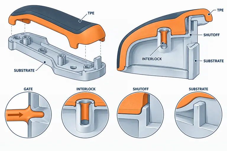
Soft-touch overmolding can improve grip, noise control, sealing, and perceived quality, but a pleasing prototype does not prove that the substrate, elastomer, interface, and production tool will remain stable. Peeling, flash, warpage, poor shutoffs, and cosmetic flow marks often begin with an incomplete material-and-interface definition.
Define the function of the soft layer first, then select an exact substrate/TPE pair, choose chemical adhesion or mechanical retention deliberately, and design locating, shutoffs, flow, venting, cooling, and ejection as one system. Validate molded assemblies after the exposures and loads that matter to the customer.
Define what the overmold must do
“Soft touch” may mean grip, a controlled feel, impact cushioning, anti-rattle contact, water management, a flexible hinge, a sealing lip, or simply a contrasting surface. Each function drives different hardness, thickness, friction, compression, wear, geometry, and test requirements. Write measurable acceptance criteria before choosing a material.
Record touch area, load direction, expected cycles, abrasion, cleaners, sunscreen or skin oils, temperature, UV, humidity, color, gloss, odor/VOC, flammability, and recycling requirements. Identify visible boundaries and class-A surfaces. If the elastomer acts as a seal, define compression range, sealing surfaces, pressure, fluid, and environmental sequence. If it is a grip, define pull, twist, peeling, and wear conditions.
Map interfaces with mating components and manufacturing steps. Paint, release agent, texture, laser marking, adhesive, welding, and prior handling can affect bond or appearance. Establish whether the substrate is molded and transferred while warm in a two-shot process or cooled, stored, and inserted for a second operation. Time, cleanliness, and surface condition can change adhesion.
The RFQ should also state annual demand, color variants, expected automation, permissible witness lines, and whether the buyer has already approved a material pair. A toolmaker cannot responsibly quote a generic soft layer without knowing whether it is decorative, load-bearing, or sealing.
Select the substrate and TPE as a tested pair
TPE family, hardness, color package, additives, and supplier grade all matter. Adhesion claims are normally conditional on a defined substrate, process window, surface cleanliness, and geometry. “TPE over ABS” or “rubber over PP” is not an orderable, validated combination. Obtain current technical and processing data for both exact grades and ask the TPE producer for compatibility guidance.
Polar substrates such as ABS or PC/ABS may pair with different TPE chemistries than low-surface-energy PP. Modified TPE grades can be formulated for specific substrates, but formulation compatibility still needs part-level proof. If the substrate changes colorant, recycled content, mold release, glass content, or source, adhesion can change. Control those inputs as part of the approved system.
Consider stiffness and shrinkage together. A soft layer contracts after molding and can bow a long, thin, or low-modulus substrate. Avient’s overmolding design guidance highlights uniform walls, gradual transitions, shrinkage/warpage, shutoffs, and mechanical interlocks as connected design issues (Avient overmolding part design). Reducing TPE thickness, stiffening the substrate, changing gate location, or selecting a different hardness may help, but each changes feel and flow.
Do not choose by hardness alone. Review service temperature, compression set where sealing matters, tear and abrasion, chemical exposure, UV, color, emissions, flow length, and processing temperature. Confirm that the substrate tolerates the overmolding thermal cycle without distortion or surface damage.
Decide how the interface will retain the soft layer
Chemical adhesion can create a clean interface, but the design should not rely on an unverified bond statement. Mechanical retention can provide a second load path through holes, slots, undercuts, edge wraps, dovetails, or captured geometry. It is especially useful near peel-prone edges, abrasion zones, or when material compatibility is uncertain.
Map load modes. Shear loading generally uses a bonded area more effectively than peel. A thin exposed edge that users can lift is vulnerable even when average bond strength is good. Terminate the TPE in a protected groove, wrap the edge, or add an interlock where practical. Avoid abrupt thickness changes that create sink, trapped air, or local shrink stress.
Use an interface review table:
| Interface question | Evidence or design response | Verification |
|---|---|---|
| Is chemical adhesion claimed for the exact grades? | current supplier compatibility and process guidance | molded peel/shear test on representative geometry |
| Where can peel begin? | protected edge, accent groove, wrap or interlock | abuse and durability inspection |
| Can fluid reach the interface? | define exposure and drainage; avoid capillary traps | conditioned assembly test |
| Does TPE shrink distort the substrate? | balance thickness, gate, stiffness and cooling | dimensional study after conditioning |
| Is retention safety- or function-critical? | independent mechanical load path where needed | specified pull, torque or pressure test |
Approval should cover the pair, not each resin independently. If either grade or surface treatment changes, apply formal change review and determine which tests repeat.
Design locating, shutoffs, gating, venting, and ejection together
Insert overmolding requires the substrate to locate repeatably without damage. Define datums, nest contact, insertion direction, orientation control, and detection of a missing or misloaded insert. The nest must account for substrate shrinkage and tolerance. Clamping a rigid insert too hard can mark or crush it; insufficient support can allow flash or movement.
Shutoffs create the visible boundary and prevent TPE from flowing over unwanted areas. They need adequate land, draft, support, and tolerance strategy. Avient notes that shutoff design must address venting, peeling, flash, and insert variation. Use spring-loaded support or other compliant methods only when mechanically justified and maintainable. Avoid knife edges that wear quickly or depend on an unrealistically perfect substrate.
Gate location controls flow length, air traps, weld lines, pressure, and orientation. Keep cosmetic gates and welds away from high-touch areas when possible, and ensure flow reaches thin edges before freeze-off. Vent end-of-fill regions without creating flash paths. Balance multi-cavity systems and define how cavity differences will be identified.
Cooling is asymmetric because the substrate and soft layer have different thermal histories. Uneven cooling can warp the assembly or extend cycle time. Ejection must support the rigid component and avoid stretching or tearing the TPE. Review undercuts, flexible lips, and texture release. If the TPE is intended to flex during ejection, confirm strain and recovery on the exact grade.
Validate process window, interface strength, appearance, and function
Mold trials should identify substrate and TPE lots, conditioning, insert age, surface preparation, cavity, temperatures, injection speed, pressure, cooling, and transfer time. A favorable sample at one setting does not establish production robustness. Deliberately test the planned process window and inspect bond, flash, short fill, burns, color, gloss, boundary definition, distortion, and ejection damage.
Create test pieces that represent the real interface and part geometry. Coupon peel data can screen combinations, but the finished part adds radii, texture, variable thickness, weld lines, and residual stress. Test the actual load direction. For a grip, include twist and pull after aging and cleaner exposure. For a seal, measure compression and leakage through the required thermal and fluid sequence. For anti-rattle pads, check wear and compression recovery against the mating surface.
Measure critical datums before and after overmolding. If a substrate is accepted before the second shot but shifts afterward, the final assembly must govern. Include cavity identity and enough samples to reveal variation. Record interface failure mode: cohesive tearing in the TPE, adhesive separation, substrate failure, or mechanical-interlock damage. The same peak force can hide different risks.
Define reaction rules for contamination, bond loss, flash at the shutoff, color variation, and insert misload. Decide which checks occur at setup, by cavity, by lot, or continuously. Preserve approved process ranges and exact material identities in the control plan.
Quote the complete overmolding system
Provide 3D and 2D files, visible surfaces, substrate and TPE specifications, hardness and color, function, interface loads, environmental duty, annual volume, cavities, automation expectation, validation, PPAP scope, and packaging. Include mating parts and explain whether the substrate is customer-supplied, molded in the same cell, or made in a separate operation.
Ask suppliers to separate substrate tool, overmold tool or two-shot tool, nests, insert handling, material trials, texture, test fixtures, external tests, and recurring molding costs. Require stated assumptions for scrap, manual loading, cycle, color change, and cavity balance. Compare proposals on the same architecture rather than only mold price.
For baseline files and commercial inputs, use the automotive injection molding RFQ checklist. Send AutoMoldingPro the grade pair and interface requirement, not a request for an unspecified “rubber coating.”
Conclusion
Successful soft-touch overmolding depends on a defined function, an exact and controlled material pair, a defensible retention path, and tooling designed around insert variation and soft-material flow. Submit CAD, grades, hardness, annual volume, visible surfaces, loads, and validation requirements through the contact page for DFM and quotation review.