
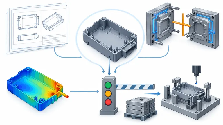
Conceptual illustration; not to scale.
A DFM report can contain dozens of screenshots and still leave the buyer unable to authorize steel. The risk is not that every concern must disappear; it is that the released CAD, mold concept, residual risks, commercial scope, and proof plan are not tied to one controlled decision.
Before tooling release, confirm the product baseline, material and use conditions, functional and cosmetic requirements, mold architecture, gates and parting, actions and ejection, cooling and venting strategy, critical tolerances, simulation assumptions, inspection method, responsibilities, and closure plan. Classify each issue as closed, conditionally accepted, or blocking, with an owner and evidence. Steel release is not trial approval or production approval.
Freeze the product intent and approval authority
The first DFM gate is configuration control. Record the exact 3D model, 2D drawing, specification, material grade, color, mating-part data, and revision being reviewed. Resolve conflicts between the model and drawing or state which source governs. ASME describes Y14.5 as the common language for expressing and interpreting GD&T on drawings, digital models, and related documents. That language only works when the datum scheme, modifiers, and acceptance interpretation are understood by design, tooling, and inspection.
Add the context that CAD cannot contain by itself: installation direction, mating sequence, loads, sealing path, no-contact and appearance zones, permissible gate and ejector witness, service access, chemical and thermal exposure, expected life, annual and peak demand, and customer approval requirements. Do not convert a general resin data sheet into a product requirement. State the selected grade and condition, then identify which properties still need component or assembly validation.
Define who can approve changes. Product engineering should own function and design intent. Tooling and molding should own feasibility proposals and identify process risk. Quality should confirm measurement and validation plans. Purchasing or the project manager should close scope, timing, and commercial effects. Customer approval may be required for specified changes. A supplier’s DFM recommendation is not authorization to alter the product.
Maintain a decision log with issue number, affected feature, evidence, proposed action, product impact, tool impact, owner, due date, and disposition. “Accepted” should identify who accepted what and against which revision. If an item remains open, state whether work can proceed around it without irreversible steel or whether the uncertainty affects the core/cavity, mold base, hot runner, action, or inspection strategy.
Review part geometry together with the mold concept
Generic checks for wall thickness, draft, ribs, bosses, radii, snap fits, threads, undercuts, and tolerances are useful only when connected to the proposed tool. The review should show parting direction, parting line, shutoffs, slides or lifters, inserts, gate type and location, runner concept, ejector locations, vent paths, cooling approach, and expected weld, sink, warp, or appearance risks. A red/yellow/green color map without a proposed disposition is not enough.
For every geometry concern, ask four questions: what failure could occur, under what material and process conditions, what change is proposed, and how will the result be verified? A thick boss may be addressed by coring, local wall adjustment, packing strategy, or accepted appearance risk. A snap arm may need draft and ejection clearance without losing retention. A sealing surface may need gate and ejector placement controlled even if the surrounding wall is moldable.
Review tolerance and datum logic before deciding where steel should be left safe. Functional dimensions should be related to the actual assembly constraint and measurement setup. The guide to deciding which tolerances need to be tight explains why interface-driven controls are more useful than tightening every dimension. Identify dimensions that can be corrected by removing steel and those that would require welding, new inserts, or a product change.
Challenge the mold against the intended press and automation. Check projected area, shot volume, plasticizing demand, mold envelope, tie bars, daylight, nozzle and locating interface, ejection, utilities, hot-runner controller, robot reach, insert loading, and part removal. A DFM approval that ignores the production cell can release a tool that molds a sample but cannot run the intended process safely or efficiently.
Make analysis and inspection assumptions reviewable
Flow simulation can support gate, fill, pack, cooling, and warpage decisions, but the report must state geometry, mesh, resin dataset, machine limits, gate and runner model, mold and melt temperatures, fill control, pack profile, cooling layout, contact assumptions, and analysis sequence. Autodesk notes that material data quality affects analysis confidence and that warp analysis depends on correct processing conditions, feed-system modeling, and preceding cool/fill/pack work. The buyer should approve the decision supported by the analysis, not a colorful plot detached from inputs.
List which simulation outputs matter to the part: pressure demand, flow hesitation, weld and air-trap location, clamp force trend, cooling uniformity, sink or volumetric shrinkage tendency, fiber orientation, or comparative warpage. Mark uncertain inputs and propose sensitivity studies where a plausible range can change the tooling decision. The separate Moldflow review guide explains detailed analysis boundaries. Retain the supplier’s actual report and assumptions in the project file.
Build the inspection concept before cutting measurement-critical features. Define datums, fixturing state, part conditioning, stabilization time, cavity identity, measurement method, sampling, appearance lighting, mating parts, functional gauges, and test responsibilities. If a critical surface deforms when clamped to a fixture, agree whether the drawing controls free state, restrained state, or an assembly condition. If nylon moisture state matters, specify it rather than measuring unconditioned trial parts against an undefined requirement.
AIAG presents APQP, Control Plan, PPAP, FMEA, MSA, and SPC as connected core tools. The DFM gate should feed later records, but it is not itself a PPAP approval. Record expected evidence now—dimensional layout, material certificate, capability study, appearance approval, functional test, run-at-rate, packaging validation—so the mold includes necessary cavity identification, gauge access, and process controls.
Separate closed, conditional, and blocking decisions
Not every open point should stop all tooling work. A useful release meeting distinguishes reversible preparation from irreversible commitment. Mold-base ordering or standard-component procurement may proceed while a non-interface cosmetic detail is being closed. Core and cavity cutting should not proceed when the governing CAD revision, shrinkage basis, gate-sensitive appearance zone, critical interface, or mold architecture remains unresolved.
Use three dispositions:
| Status | Meaning | Required record |
|---|---|---|
| Closed | Requirement and solution are approved for the released baseline | Revision, decision, approver and evidence |
| Conditional | Work may proceed within a stated boundary while a defined item closes | Condition, protected steel/work scope, owner, date and fallback |
| Blocking | Irreversible tooling work would create unacceptable risk | Reason, missing input, decision owner and next review |
Conditional approval must be specific. “Proceed at risk” is not a control. State which steel must remain untouched, which components may be ordered, the cost and timing exposure, and what happens if the final answer changes. A steel-safe dimension may permit adjustment in one direction, but confirm the geometric relationship; not every dimension can be corrected by removing steel.
Distinguish later gates. Tooling release authorizes the defined manufacturing work. Trial approval accepts a particular sample or authorizes the next correction under documented conditions. Production approval accepts the product and process evidence required by the customer. The existing T1 versus production-release article explains why acceptable early samples do not automatically release serial production.
Buyer’s tooling-release checklist
- Controlled 3D, drawing, specifications, material grade, color, and mating data agree.
- Functional interfaces, datums, critical characteristics, cosmetic zones, and use conditions are marked.
- Parting, gates, runners, actions, ejection, venting, cooling, cavity count, and cavity identification are reviewed.
- Production press, automation, inserts, secondary operations, gauges, packaging, and maintenance access are considered.
- Simulation inputs, limitations, decisions, and required trial correlation are recorded.
- Inspection state, methods, fixtures, sampling, and later validation evidence are defined.
- Tool ownership, data, spares, change authority, responsibilities, price, and timing effects are closed.
- Every issue is closed, conditionally accepted with a boundary, or blocking.
- The signed release names the exact revision and does not claim trial or production approval.
Use the checklist as a release record, not as a meeting agenda that disappears afterward. For each item, name the controlled document, revision, owner, status, remaining action, due date, and approval authority. Attach marked drawing views when a written comment could be interpreted in more than one way. If a decision depends on a later trial, state the temporary geometry or steel allowance that preserves the option and the evidence required to close it. The record should let a person who missed the review understand what was accepted, what remains conditional, and which change would trigger another DFM review.
Illustrative example: a visible housing has a mounting boss opposite a Class A surface. The supplier predicts sink and proposes thinning the boss, but assembly engineering has not confirmed screw engagement and pull-out needs. The team records the issue as blocking for that insert region while allowing mold-base procurement to continue. It compares coring, local wall transition, gate and cooling changes, and an appearance concession against the controlled load and surface criteria. Only the approved option and its inspection evidence are released to steel.
Send the supplier the STEP model, 2D drawing, material and color requirement, mating sections, cosmetic map, annual demand, target press, inspection plan, and customer submission needs. For an automotive DFM review tied to an actual tooling decision, use the AutoMoldingPro DFM service or submit the controlled package through the RFQ page.