
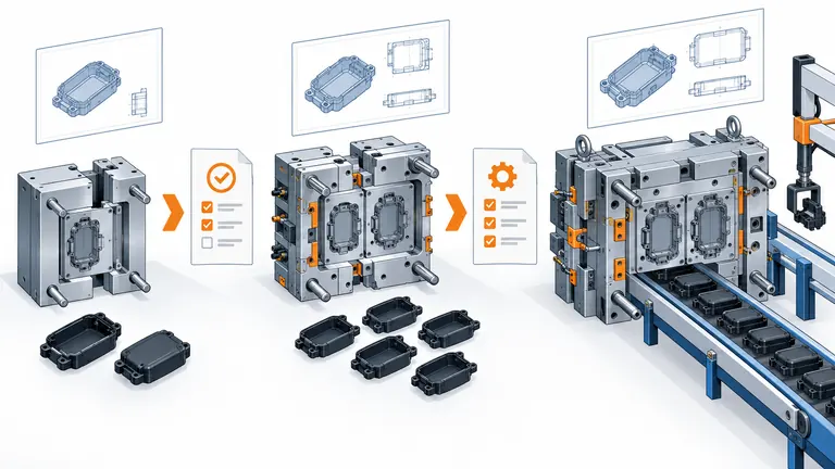
A low-cost mold can be wasteful if the design changes before validation, while a full production tool can arrive too late to support builds. The labels “prototype,” “bridge,” and “production” are not specifications. Buyers need to connect each tool to the parts, evidence, quantity, and changes expected at that stage.
Choose the tooling stage by the decision the molded parts must support. Prototype tooling should answer defined design or process questions. Bridge tooling should supply a controlled temporary quantity while design, validation, or production capacity is completed. Production tooling should meet the approved demand, process, maintenance, automation, and customer-release requirements. Tool material alone does not determine the category.
Define the purpose before selecting the tool
The same molded geometry may be needed for fit checks, environmental testing, pilot assembly, customer submission, launch stock, or serial supply. Those uses impose different requirements. A tool should therefore be specified by intended evidence and operating window, not by an informal category name.
Begin with a build-and-decision map. For each required quantity, record the part revision, material grade and condition, required process similarity, test or assembly use, dimensional evidence, cosmetic requirement, traceability, due date, and approving party. If parts will support a regulated or customer approval, confirm whether that customer accepts samples from the proposed tool and process. A part made in production resin is not automatically production representative if gate location, cavity pressure, cooling, ejection, secondary operations, or inspection methods differ.
Prototype tooling is appropriate when learning is the main output. It may test moldability, assembly, sealing interfaces, clip behavior, or appearance feasibility. The design can still change, and lower cavitation, manual inserts, simplified cooling, or limited automation may be acceptable when documented. However, the buyer must decide which results can transfer to the production process and which must be repeated.
Bridge tooling is a deliberate temporary supply path. It can support pilot builds, early demand, a delayed production tool, repair coverage, or a staged investment. Protolabs describes bridge tooling as a way to produce parts while production tooling is being made, but also notes that rapid tooling may not incorporate every production-tool feature, such as more sophisticated cooling or venting. That boundary is why a bridge tool needs its own approved use and exit plan (Protolabs bridge-tooling guidance).
Production tooling must be evaluated as part of a repeatable manufacturing system. Cavitation, steel and hardness, cooling, runner system, wear areas, sensors, ejection, machine interfaces, automation, spare strategy, maintenance access, and cavity traceability should support the approved volume and life-cycle plan. “Steel tool” alone does not prove this capability.
Match design maturity to reversible and irreversible spending
Tooling decisions become expensive when steel removal, texture, complex actions, or dedicated automation make changes difficult. The buyer should identify which product decisions are stable enough to justify each irreversible step.
Use controlled maturity gates. Before a prototype tool, the team may accept open cosmetic, tolerance, or interface questions if the tool is explicitly intended to study them. Before bridge tooling, the mating envelope, material family, gate-sensitive functions, and test use should be sufficiently stable that the temporary parts remain meaningful. Before production-tool release, the controlled CAD and drawing, datums, critical characteristics, material grade, appearance zones, assembly interfaces, expected volume, and validation responsibility should be closed or formally conditionally approved.
Do not confuse a calendar deadline with design maturity. If an unclosed connector interface could move a shutoff or slide, starting the production tool early may create more delay than waiting for the interface decision. A useful DFM record marks each item closed, conditionally approved, or blocking and identifies the evidence needed to change status. The buyer’s tooling-release checklist provides a separate gate for that decision.
Steel-safe planning can preserve some correction direction, but it is not a substitute for mature requirements. It may permit selected dimensions to be adjusted by removing steel later; it cannot make every geometry change inexpensive, and it can conflict with appearance, shutoff, cooling, or structural needs. Identify each intended adjustment feature on the mold review, including the plastic-dimension direction and the amount reserved, without claiming that all deviations are recoverable.
Texture, final polish, coatings, and dedicated gauges should follow the appropriate approval sequence. If a bridge tool is being used for cosmetic decisions, confirm whether its surface, molding process, and resin color system can represent the production result. Otherwise, use it for fit or functional learning and reserve final appearance approval for production-intent conditions.
Compare capability gaps, not category labels
Two suppliers may both call a tool “bridge,” yet one proposes hardened inserts and controlled cooling while another proposes a manual, low-cavitation tool. Compare the actual capability against the part-use map.
| Decision factor | Prototype tool | Bridge tool | Production tool | Evidence to compare |
|---|---|---|---|---|
| Primary purpose | Learn about design/process | Temporary controlled supply | Approved repeat production | Build and decision map |
| Expected revisions | Likely | Limited and managed | Controlled through formal change | Open-issue register |
| Quantity basis | Samples/tests | Defined interim demand | Program demand and service plan | Dated volume scenarios |
| Process similarity | Only what the test needs | Enough for approved temporary use | Production-intent cell and controls | Machine, runner, cooling, automation plan |
| Cavitation | Often low | Based on temporary capacity | Based on demonstrated good-part capacity | Capacity calculation and trial plan |
| Tool life/maintenance | Limited use stated | Interim window and spares | Life-cycle maintenance strategy | Materials, hardness, wear and spare list |
| Validation | Question-specific | Approved temporary evidence | Customer-required release | Test matrix and submission plan |
| Exit condition | Learning complete | Production tool approved or risk retired | End of program/authorized change | Named acceptance gate |
Ask for a deviation list from the intended production system. It should cover tool material and hardness, gate and runner, cavity count, cooling layout, ejection, manual operations, molding machine, auxiliary equipment, secondary processes, inspection method, and packaging. For every difference, identify the decision it could affect. This is more useful than arguing whether aluminum or prehardened steel always belongs to one category.
Capacity must be expressed as acceptable parts over available time. Review cycle assumptions, cavities actually running, expected yield, planned maintenance, changeovers, labor or automation, downstream operations, and inspection. A bridge tool that cannot meet the temporary schedule is not a bridge; it is another delay. A production tool that meets peak volume only at theoretical cycle and perfect yield is not yet a credible serial plan.
Also compare transferability. Will the process window, inspection fixture, packaging, and lessons from the temporary tool be captured for the production team? Which dimensional results must be re-established because the gate, cooling, cavity, or machine changes? The plan should prevent temporary-tool approval from being copied into production records without review.
Use a staged quantity and cost model
The economic comparison should include both tooling spend and the cost of time, change, duplicated validation, temporary unit price, inventory, and transition. A cheap temporary tool can become expensive if its parts cannot support the required tests or if it delays learning about the production process.
Illustrative example—hypothetical and not an AutoMoldingPro quotation. A program needs 2,000 molded parts for assembly learning, then 25,000 parts during a production-tool lead-time window, followed by serial demand. The design team expects one interface revision before final release. Three scenarios could be compared:
- release the production tool immediately and budget a likely modification;
- build one prototype tool for the 2,000 learning parts, then release production tooling after the interface closes;
- build a bridge tool capable of all 27,000 pre-serial parts, with a defined transition to production tooling.
The team should not choose from tool prices alone. It should calculate cash by date, temporary and serial piece prices, expected modification exposure, duplicate inspection or validation, production-tool completion date, and shortage risk. Use ranges for uncertain changes rather than pretending the probability is known exactly. If the bridge tool becomes a backup tool, include the inspection, storage, maintenance, and requalification work needed to keep that role credible.
A stage-gate table should show the maximum approved quantity and use for each tool. For example, “engineering assembly only” is different from “customer saleable parts.” If the project requires a deviation or interim approval, the authorized customer process governs. AIAG’s APQP resources emphasize gated management, sourcing, change management, and risk mitigation; the project should apply the customer-specific requirements that actually govern it rather than treating a generic article as approval.
Plan the transition before ordering temporary tooling
Bridge strategies fail most often at the handoff. The temporary process accumulates lessons, but the production-tool team receives only final CAD. A transition package should convert those lessons into controlled inputs.
Maintain a shared issue log covering design changes, moldability observations, dimensional trends, assembly feedback, material handling, cosmetic boundaries, inspection methods, packaging, and process-sensitive features. For each item, state whether it is incorporated in production CAD, production mold design, control plan, gauge, work instruction, or validation plan. Attach evidence rather than relying on meeting memory.
Before production-tool trials, create a delta review between temporary and production systems. Compare cavity count, gate, runner, cooling, machine, process window, ejection, automation, secondary work, inspection, and material lot/state. Then decide which results can be referenced and which must be repeated. Do not use a passing test from the temporary tool to close a risk caused by a different production condition.
Define the temporary tool’s end state. It may be scrapped, stored, transferred, retained for service, or qualified as backup. Each option has cost and control implications. If retained, identify ownership, location, preservation, maintenance, drawings, spare parts, allowed materials, last approved process, and reactivation requirements. If it is not capable of interchangeable production, label that limitation clearly.
For an RFQ, send the controlled CAD and drawing, the build-and-decision map, quantities by date, allowed material and process differences, expected design freezes, validation uses, production volume, machine destination, and transition requirements. Ask suppliers to return a tool-specific capability and deviation matrix, not only a category and price.
Conclusion
Select prototype, bridge, or production tooling by the evidence and quantity required at each maturity stage. Define process differences, approved part use, capacity, change exposure, and the transition package before award. The best staged plan is the one that retires the right risk without allowing temporary evidence to masquerade as production approval.