
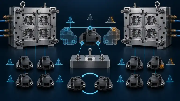
Conceptual illustration; not to scale.
A duplicate mold can match the original CAD and still produce a meaningfully different part. Steel dimensions are only one influence; resin lot, machine, cooling, cavity layout, gate behavior, process window, measurement method, and assembly conditions can all change the result. Calling the new tool “identical” before comparison hides those sources of variation.
Qualify the duplicate by comparing both tools under a documented, risk-based plan. Use the same released product definition and measurement system, identify tool and cavity for every sample, control or deliberately account for material and process differences, compare dimensions and functions, challenge the process window, and obtain the customer approval required for the new source or tool. The goal is not zero numerical difference; it is demonstrated conformance and interchangeability for the intended use.
Define what “equivalent” must mean for the program
The word duplicate describes design intent, not acceptance. Before trials, translate it into decisions that engineering, quality, purchasing, production, and the customer can approve. A capacity backup may require interchangeable parts from either tool; a regional tool may use a different machine; a service tool may have lower volume but the same functional requirements.
List the intended operating scenarios. Can parts from Tool A and Tool B be mixed in one assembly lot? Will they run at different plants or with different approved materials? Must appearance match across visible neighboring parts? Are cavity identities traceable? Does either tool support only a subset of variants? These questions determine whether conformance by itself is enough or whether a direct two-tool comparison is necessary.
Set acceptance in layers. First, every part must meet the released drawing, specifications, regulatory and customer requirements. Second, critical interfaces and functions must remain compatible with mating parts and assembly operations. Third, process outputs must be stable over the planned window and rate. Fourth, appearance, packaging, traceability, and handling must satisfy the actual use. Finally, the submission and change-approval route must be completed.
Do not create an arbitrary blanket rule such as “all dimensions within 10% of each other.” A small difference can matter at a latch or seal while a larger difference may be harmless on an unconstrained surface. Tie comparison limits to function, tolerance, measurement uncertainty, historical variation, assembly needs, and customer direction.
Establish a common baseline before comparing parts
A two-tool study is difficult to interpret when everything changes at once. The team should align the released data, materials, conditioning, measurement system, sampling logic, and time basis before comparing tool outputs.
Confirm that both tools represent the same approved part revision. Review steel-safe conditions, approved deviations, intentional tool-specific offsets, cavity numbering, gate type, cooling layout, texture, engraving, and inserts. If Tool B intentionally differs—for example, to fit another press—record which differences can influence the part.
Use the same resin producer and grade where the qualification objective requires it, preferably from a traceable common lot. Control drying, color or additive, regrind, packaging, and moisture-sensitive conditioning. If regional material or color sources are part of the objective, structure them as separate factors rather than blending them into the tool comparison.
Define the measurement plan before seeing results. Use the same datum alignment, fixture, program, instrument class, environment, conditioning time, operator method, and rounding rule. Verify that the measurement system is suitable for the tolerance and decision. ASME Y14.5 defines the drawing language, while the actual equipment selection and uncertainty still require a measurement plan appropriate to the feature.
Select a traceable reference set from the approved original tool, but do not let retained samples override the released requirements. Record age and storage condition, especially for moisture-sensitive or dimensionally changing polymers.
Design samples that preserve tool, cavity, and process identity
An average across all cavities can hide one cavity that is biased or unstable. Sample identity should allow the team to separate tool-to-tool, cavity-to-cavity, time-related, and measurement variation.
Create a matrix covering Tool A and Tool B, every active cavity, the nominated process condition, startup and steady-state periods, and any approved low/high window points. Mark each part with tool, cavity, machine, date, material lot, trial stage, and cycle or time block. Avoid mixing untraceable parts in a single bag.
The number of parts should follow risk, cavity count, characteristic type, expected variation, measurement cost, and customer requirements—not a universal internet sample size. Dimensional characteristics may need repeated observations over time; destructive tests need a separately justified plan; appearance can require controlled lighting and approved boundary samples. A run-at-rate or capacity study answers a different question and should be planned separately when needed.
Use production-intent conditions for the formal comparison. Development settings may be useful for learning, but they should not be reported as production evidence without qualification. Stabilize the mold and process under a defined rule before collecting the main sample, while retaining startup evidence where startup scrap or thermal behavior matters.
Record actual process outputs alongside setpoints: fill time, transfer, cushion, peak pressure, hold behavior, recovery, melt and mold temperatures, cooling flow, cycle time, part and runner weight, alarms, and rejects. This makes a dimensional difference investigable rather than merely observable.
Compare in four layers: conformance, bias, variation, and function
Use four separate questions because a single pass/fail summary is not enough. A tool can produce conforming averages while one cavity is unstable; two tools can have different means while both remain functionally robust; a dimensional pass can still fail assembly.
| Comparison layer | Main question | Evidence | Typical response |
|---|---|---|---|
| Conformance | Does each tool meet released requirements? | Dimensional, material, appearance and test results | Correct any nonconformance before equivalence approval |
| Bias | Is one tool or cavity consistently shifted? | Cavity plots, paired feature summaries, reference comparison | Assess function and steel/process correction need |
| Variation | Is output stable over time and conditions? | Time-order plots, process traces, capability evidence when valid | Remove special causes and confirm process window |
| Function | Are parts interchangeable in actual use? | Assembly, fit, sealing, retention or other specified tests | Approve, contain, or redesign the interface decision |
Plot results by tool and cavity rather than presenting only pooled statistics. Review critical features first, then the remaining drawing and control-plan requirements. Report measurement uncertainty or resolution where it can affect the decision. Capability indices are not a substitute for stability, a suitable measurement system, rational sampling, and agreed specification interpretation.
For assemblies, plan combinations that reflect actual mixing risk: Tool A part with mating source 1, Tool B part with source 1, and other approved combinations where relevant. Do not invent a functional test simply because dimensions differ. Use the product requirement or an engineering-approved evaluation with defined acceptance.
Challenge the duplicate tool’s usable process window
Matching one center-point trial does not show that Tool B will remain acceptable through routine variation. The qualification should establish enough robustness for intended production without using process changes to conceal steel, venting, cooling, or balance problems.
Begin with a scientific fill assessment and balanced transfer strategy appropriate to the part. Compare fill pattern, cavity balance, pressure demand, shear-sensitive appearance, weld-line location, gas traps, and gate freeze behavior. Confirm cooling balance and ejection. If hot runners or valve gates differ, verify zone and sequence behavior under their supplier-supported controls.
After the nominated process is stable, challenge selected low and high conditions within an approved, technically safe study. The factors may include fill rate, hold pressure or time, cooling, mold temperature, or another known control, but they should be chosen from risk analysis rather than changed mechanically. Keep material and measurement conditions controlled. The objective is to identify a defensible operating region, not to find settings that make one sample pass.
Separate tool corrections from process compensation. If Tool B requires a narrow or unusual setting to hold a critical feature, document the risk and consider a steel, gate, vent, cooling, or component correction. The steel-safe tooling approach can preserve correction direction on selected features, but it does not replace qualification after the change.
When production rate matters, complete the agreed capacity evidence after the process window is established. A duplicate tool that makes good samples at a slow development cycle is not automatically ready for scheduled volume.
Use a two-tool qualification matrix
This matrix turns the study into auditable release gates. Tailor rows to the program and name the approval owner for each.
| Gate | Tool A evidence | Tool B evidence | Direct comparison | Acceptance owner |
|---|---|---|---|---|
| Released design and change level | Revision confirmed | Revision confirmed | Differences listed | Product engineering |
| Tool condition and interfaces | Baseline recorded | New-tool record complete | Intentional differences assessed | Tool engineering |
| Material and process traceability | Trial record | Trial record | Factors controlled or separated | Process engineering |
| Measurement system | Method confirmed | Same method used | Uncertainty and alignment reviewed | Quality |
| Dimensional conformance | By cavity | By cavity | Bias and variation reviewed | Quality/product engineering |
| Appearance and function | Approved evidence | Production-intent evidence | Interchangeability evaluated | Customer/design authority |
| Process window and rate | Reference data | Study completed | Risks and limits documented | Manufacturing |
| Submission and release | Current approval | Required submission complete | Mixed-use rule defined | Customer/SQE |
Attach raw results, not only green/red cells. Each exception needs disposition, containment, responsible owner, and approval. Preserve the matrix as the baseline for repeat orders and later changes.
Illustrative example: adding a backup mold for a latch housing
This illustrative example is a decision model, not a customer case. A buyer commissions Tool B to support a latch housing currently produced in a four-cavity Tool A. The parts may be mixed at assembly, and retention force depends on a snap feature and two mounting datums.
Both tools use the same released revision and resin lot during comparison. Samples are segregated by cavity and time block. The pooled dimensional report passes, but cavity B3 shows a consistent shift at one mounting datum. All readings remain within print tolerance, yet a mixed assembly trial reveals less clearance with one extreme mating component.
The team does not declare the tool equivalent from the pooled pass. It reviews datum alignment, measurement uncertainty, forming steel, cooling, and process traces for B3. Engineering confirms that the observed stack is undesirable even though individual dimensions pass. A controlled steel correction is made, Tool B is retried by cavity, and the mixed assembly matrix is repeated.
Release occurs only after individual-tool conformance, cavity stability, functional interchangeability, and the customer-required submission are complete. The study also defines traceability rules so any future issue can be separated by tool and cavity.
Evidence to request from the duplicate-tool supplier
- released part and tool data with revision and approved differences;
- tool build, component, steel, hot-runner, cooling, sensor, and machine-interface records;
- trial material, machine, auxiliary, process outputs, cycle, cavity balance, and reject records;
- cavity-identified dimensional results and raw measurement files;
- measurement method, fixture, alignment, calibration status, and measurement-system evidence;
- appearance boundary samples and specified material or functional test results;
- process-window, maintenance, spare-part, and expected-life assumptions;
- corrective-action records for every failed or shifted characteristic;
- required PPAP or customer-specific submission and signed release status.
Treat unverified claims of “same steel” or “same dimensions” as items to confirm through records and inspection, not as qualification evidence.
Conclusion
Qualify a duplicate tool by proving conformance, stability, and intended interchangeability—not by comparing CAD names or one sample. Send AutoMoldingPro the released requirements, Tool A baseline, Tool B build data, material plan, destination-machine details, critical-characteristic list, and customer approval route to structure a two-tool comparison.