
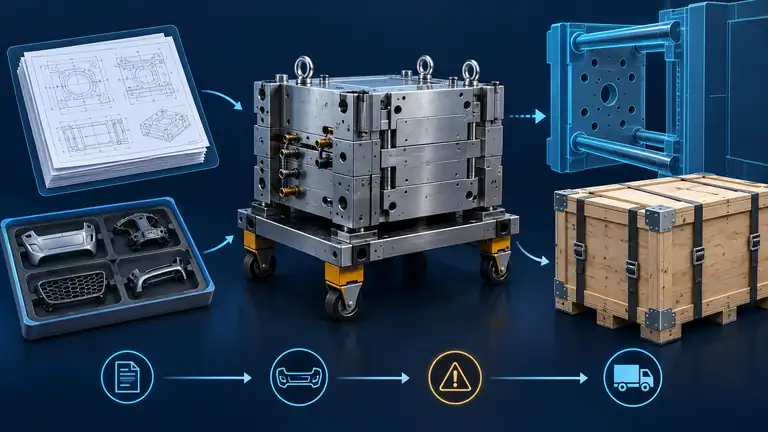
Conceptual illustration; not to scale.
A mold can be physically ready to load on a truck while the production transfer is still unprepared. Missing interface data, uncertain ownership, an undocumented repair, or the wrong reference sample can turn a normal relocation into a launch problem at the receiving plant. The safest transfer treats the tool, product definition, process baseline, and approval route as one controlled package.
Before moving the mold, verify authority to transfer it, current tool condition, released product and process records, destination-machine compatibility, auxiliary connections, reference parts, open quality issues, preservation and transport controls, and the receiving trial plan. A successful shipment transfers custody; a successful production transfer also demonstrates that the receiving process can reproduce the agreed part and evidence under the applicable customer requirements.
This checklist assumes the main CAD, drawings, process records, and ownership documents are substantially available. When those records are incomplete, use the separate recovery approach in transferring an automotive mold without complete CAD or process records.
Establish transfer authority, scope, and decision owners
Do not schedule removal until the parties agree who can authorize access, shipment, repair, copying, and production. A purchase order that paid for tooling does not by itself answer every custody, intellectual-property, lien, storage, or use question across jurisdictions. Use the actual contract, purchase documents, tool register, customer instructions, and legal advice applicable to the parties.
Create a transfer authorization record with the tool number, customer and part numbers, current location, sending and receiving organizations, planned shipment date, owner or authorized controller, and approved purpose. State whether the move is temporary, permanent, for repair, for a capacity study, or for production. List product data, software, gages, fixtures, spare inserts, hot-runner controllers, and customer-owned materials that travel separately from the mold.
Name the decision owners. Purchasing controls the commercial instruction; engineering controls the released design; quality controls the baseline and submission plan; the sending molder controls safe removal and records; the receiving molder confirms interfaces and trial readiness; the customer or design authority approves any required source or process change. One person may hold several roles, but the decisions should not disappear into an email chain.
Confirm confidentiality and data-transfer limits before copying files. Identify export-control, customs, tax, or import responsibilities through qualified professionals where they apply. This article is an operational checklist, not a universal legal opinion.
Record the tool’s actual condition before removal
The receiving plant needs the current condition, not the condition described when the mold was new. Perform a joint incoming-style inspection at the sending site before disconnection, preferably with dated photographs and cavity/component identification.
Inspect mold plates, locating and clamping features, leader pins and bushings, interlocks, parting lines, shutoffs, slides, lifters, ejectors, return systems, springs, hydraulic or pneumatic cylinders, hot-runner components, wiring, heaters, thermocouples, water circuits, connectors, safety straps, lifting points, and identification plates. Check for corrosion, leakage, blocked circuits, damaged threads, temporary shims, welded areas, missing fasteners, bypassed sensors, and nonstandard repairs. Record mold weight and center-of-gravity information where available; do not estimate lifting safety from external dimensions.
Run the mold at the sending plant if it is safe and commercially possible. Preserve cavity-marked samples, cycle data, actual process settings, alarms, scrap observations, and the quality results. A running sample does not prove the mold is healthy, but it gives the receiving plant a point of comparison. If a send-site trial cannot be performed, state that limitation and increase the receiving inspection and trial scope.
Classify every finding as accepted current condition, repair before shipment, repair after receipt, monitored wear, missing evidence, or production stop. Attach an owner and due date. Avoid phrases such as “normal wear” without a location, measurement, photograph, or agreed disposition.
Build the technical handover package
The handover package should let a competent receiving team identify the product, assemble and service the mold, connect it safely, establish a starting process, and understand what evidence previously earned approval. It does not need to be one enormous file, but it needs a controlled index.
Include released 3D and 2D product data, mold assembly and component drawings, cavity and insert maps, bill of materials, steel and heat-treatment records where available, hot-runner drawings and manuals, electrical and fluid schematics, spare-parts list, maintenance history, modification history, mold-flow or DFM records that still affect the process, and the current tool revision. AIAG’s CQI-33 describes a technical data package as files and associated data used for product-design exchange; the practical lesson is that filenames without revision, authority, and relationships are not a controlled package.
Include the process baseline: machine make/model and injection unit, screw diameter, resin manufacturer and exact grade, color/additive, drying requirements, mold and melt conditions, injection profile, transfer method, cushion, pressure limits, cooling and cycle breakdown, startup/shutdown instructions, cavity status, auxiliary equipment, robot or manual handling, and approved packaging. Mark values as setpoints, actual ranges, or reference-only observations.
Include the quality baseline: released drawing, special characteristics, control plan, PFMEA link or applicable risk record, inspection instructions, gage and fixture definitions, measurement-system evidence, capability or run-at-rate records where applicable, visual standards, approved reference samples, nonconformance and deviation status, and the customer’s required resubmission or notification route.
Verify the destination press and auxiliary interfaces
Matching clamp tonnage is not a compatibility review. Compare the actual mold envelope and weight with tie-bar spacing, platen size, mold-height range, daylight, opening stroke, ejector force/stroke and pattern, nozzle radius and orifice, locating ring, bolt or clamp pattern, injection-unit shot volume and pressure/flow capability, and mold-loading route. Confirm whether rotating tie bars, magnetic platens, quick clamps, or adapters change the available space.
Map water, oil, air, electrical, thermocouple, hot-runner, valve-gate, core-pull, robot, and safety interfaces. Record thread/quick-coupler type, quantity, flow direction, pressure rating, voltage, frequency, connector pinout, cable length, and controller ownership. EUROMAP’s technical recommendations show why mold fixing, ejection, core pull, hot-runner, and handling interfaces are separate compatibility topics.
Use a signed interface sheet:
| Interface group | Mold evidence | Destination evidence | Acceptance before shipment |
|---|---|---|---|
| Envelope and loading | Mold drawing, weight, lifting points, center of gravity | Tie-bar spacing, crane/loader, guarding, route | Safe loading and full travel demonstrated on paper |
| Clamp and location | Base dimensions, locating ring, clamp slots/holes | Platen and clamping method | No unapproved adapter or interference |
| Open/eject | Mold height, required opening, ejector geometry and stroke | Daylight, stroke, force and coupling | Part/runner can release without collision |
| Injection/nozzle | Sprue/nozzle interface, shot requirement, pressure/flow history | Injection-unit and nozzle data | Compatible contact and adequate reviewed capacity |
| Utilities/control | Circuit map, voltage, connectors, hydraulic/pneumatic demand | Plant supplies and controllers | Correct adapters, cables and safe functions available |
For an export mold designed for a destination press, the more detailed machine-fit method is covered in will an export automotive mold fit the destination injection molding machine?.
Define the baseline sample and receiving trial
A reference sample is useful only when its identity and approval meaning are clear. Label part number, revision, cavity, material, date, process source, and status. Distinguish a visual master, dimensional reference, functional sample, boundary sample, and customer-approved production part. One sample may not represent all cavities or all characteristics.
Before shipment, agree which characteristics will be compared at the receiving trial and which tests must be repeated. At minimum, check fill, flash, appearance, ejection, part weight, cycle stability, critical dimensions, assembly/functional interfaces, and cavity balance as applicable. Use the same measurement method and sample state where results are expected to be comparable.
Define the trial material, machine, setup, sample quantity, cavity coverage, stabilization rule, inspection timing, reporting format, and approval owner. Identify what happens if the receiving process cannot reproduce the baseline: process-development work, mold maintenance, interface correction, design review, or customer disposition. A first complete shot should not automatically release production.
State which characteristics must be compared by cavity and which observations are informational only. This prevents one pooled pass/fail summary from hiding a transfer-related cavity shift and gives the receiving team a defined escalation path.
The IATF Rules Q&A states that relocation or significant change must be communicated within the certification framework so the certification body can determine appropriate action. Product/customer notification is a separate matter governed by the applicable customer-specific requirements and contracts. Do not treat certification-body notice as customer production approval.
Control preservation, transport, receipt, and restart
Drain and dry cooling circuits according to the tool and component instructions. Clean residue without damaging surfaces, apply compatible corrosion protection, secure moving components, cap ports, protect connectors, fit transport bars, and use a crate or support designed for the actual mass and lifting method. Photograph the protected condition and seal identification.
The shipping pack should include packing list, gross/net weight, dimensions, lifting instructions, center-of-gravity marking where available, customs description, destination contact, shock/tilt indicators if specified, and a list of items shipped separately. Do not place the only copy of the technical package inside a crate that may be delayed or damaged.
At receipt, compare seal and crate condition, tool identity, packing list, corrosion protection, moisture indicators if used, loose components, connectors, and visible transport damage. Record discrepancies before cleaning or installation. Perform the planned incoming inspection and safe function checks before molding resin.
Illustrative example: a four-cavity housing mold is moved between qualified suppliers with drawings and process records available. The interface review finds that the receiving press has adequate clamp force but a different ejector coupling and hot-runner connector. The team prepares approved adapters before shipment, labels the reference samples by cavity, and schedules dimensional comparison after a stable receiving run. The move stays a normal transfer because the gaps are found before the truck arrives.
Transfer release checklist
Use this condensed gate only after the supporting evidence exists:
- Transfer authority, custody, confidentiality, destination, and scope are documented.
- Tool condition, open repairs, cavity status, and modification history are recorded.
- Product, mold, process, maintenance, quality, gage, and approval records are indexed.
- Destination press, loading route, utilities, controls, robot, nozzle, and ejector interfaces are checked.
- Reference samples and their approval meaning are identified.
- Preservation, packing, lifting, shipping, insurance, customs, and receipt responsibilities are assigned.
- Receiving inspection, trial, comparison evidence, customer notification, and production-release gates are approved.
For a transfer feasibility review, provide the mold assembly, current location, destination machine data, part drawing, resin, annual demand, current process sheet, recent sample/quality evidence, and required transfer date through the automotive mold transfer and repair service or request a transfer assessment.
Conclusion
Release a normal mold transfer only when authority, actual tool condition, records, destination interfaces, reference evidence, transport controls, and receiving validation are connected in one plan. Shipping the mold is a logistics event; reproducing the approved part and completing the required customer gates is the production-transfer decision.
References
- AIAG, Quality Core Tools — roles of APQP, Control Plan, PPAP, FMEA, MSA and SPC in product and process evidence.
- AIAG, 3D Model Technical Data Package Exchange Guideline — controlled exchange of design files and associated technical data.
- IATF, Rules 6th Edition Q&A on relocation and significant change — certification-body communication boundary for relocation.
- EUROMAP, Technical Recommendations for Injection Molding — mold fixing, ejection, core-pull, hot-runner and handling interface references.