
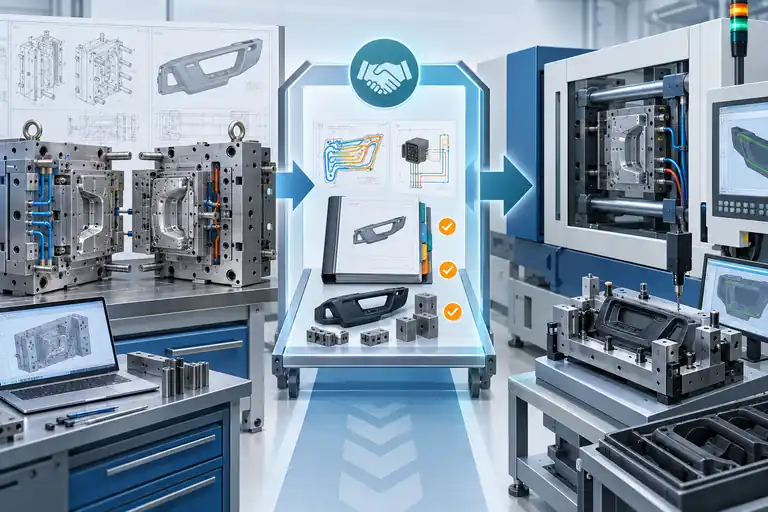
Buying a mold from one supplier and serial parts from another can preserve sourcing flexibility, but it also creates an interface that neither purchase order controls by itself. A mold can produce acceptable samples at the toolmaker yet arrive at the production molder with incompatible connections, incomplete process evidence, unclear correction ownership, or no approved baseline for restart.
The arrangement works when the customer appoints one technical owner, involves the receiving molder before mold design is frozen, and separates three approvals: tool design release, source-site acceptance, and production-site release. The handoff package must cover machine and utility compatibility, drawings and software, approved material and samples, a reproducible process window, open issues, spares, shipping protection, and responsibility for requalification. A good T1 part alone is not evidence that the production system is ready.
This guide is for program managers and tooling buyers who have already chosen separate suppliers and need to make the boundary executable. It does not compare export tooling with supplier-held production as a sourcing model.
Define One System Boundary Before Either Supplier Quotes
The first decision is not which company owns which task. It is what constitutes the delivered production system. If the tooling purchase stops at “mold makes parts,” while the molding purchase starts at “customer supplies mold,” the machine interface, auxiliaries, inspection assets, process knowledge and correction loop can fall between contracts.
Create a system-boundary schedule before nomination. Identify the sellable part revision, resin and color, mold, hot-runner controller, valve-gate or core-pull equipment, cooling and temperature-control needs, robot or removal method, post-mold operations, gauges, packaging and production records. For each item, name the design owner, purchaser, acceptance owner, delivery destination and change authority. A customer-owned item still needs an operational owner.
Bring the intended production molder into the tool specification review. The receiving team should confirm platen and tie-bar fit, mold thickness range, locating ring and sprue interface, ejector pattern and stroke, required opening distance, shot and plasticizing demand, clamp-force basis, lifting access, water quality and connector standards, electrical voltage and connector pinout, pneumatic or hydraulic services, hot-runner zones and robot interface. These are project-specific checks, not universal mold dimensions. The PLASTICS Industry Association’s robot/IMM interface guideline illustrates why equipment interfaces must be identified rather than assumed.
The boundary should also state what the toolmaker is not validating. A trial on a different press, controller, dryer, mold-temperature unit, resin lot or automation arrangement can prove part geometry under that trial condition, but it cannot automatically prove the receiving cell. Conversely, the production molder should not treat every restart difference as a tool defect. Both suppliers need the same list of controlled inputs and acceptance outputs.
| Boundary item | Tooling supplier responsibility | Production molder responsibility | Customer decision |
|---|---|---|---|
| Mold interfaces | Design and document actual interfaces | Confirm fit to intended cell before release | Approve exceptions |
| Trial process | Record material, machine and settings | Review transferability and propose receiving trial | Define evidence required |
| Part acceptance | Supply identified samples and results | Reproduce and inspect at receiving site | Approve baseline and open points |
| Corrections | Correct agreed tool nonconformities | Correct cell, setup or handling causes | Resolve disputed cause and cost |
| Production release | Support handoff | Demonstrate stable production-intent process | Authorize serial supply |
Use the table as a contract index. Each row should point to a drawing, checklist, test plan or acceptance record; labels such as “complete tooling” are too broad to enforce.
Freeze the Technical Interfaces Before Steel Completion
Late interface discovery is expensive because it can require machining finished plates, rerouting water, replacing connectors, changing controller hardware or reducing the available molding envelope. A receiving-molder review made only after shipping turns compatibility into a recovery project.
Issue an interface control document with the mold layout. Include mold mass and center of gravity, maximum envelope, lifting points, clamp slots or bolt pattern, locating features, nozzle seat, minimum and maximum mold height, opening sequence, ejector arrangement, core-pull sequence and interlocks. Map every water circuit by inlet, outlet, flow direction and target service. Identify hot-runner zones, heater and thermocouple wiring, connector type, voltage, controller requirement and spare components. Label pneumatic and hydraulic ports by function and safe state.
Documentation does not replace physical verification. Before source-site acceptance, check labels against the actual mold, flow-test cooling circuits, verify that moving actions complete without binding, and confirm electrical continuity and zone mapping using the equipment supplier’s instructions. DME’s hot-runner system start-up guide calls for electrical and thermocouple checks before production connection; the applicable limits and procedure must come from the installed system documentation, not from a copied generic checklist.
Review handling and maintainability as interfaces too. The receiving plant needs safe lifting access, support feet where components protrude, access to filters and wear items, an understandable lubrication plan, and replaceable components that can be sourced or manufactured. If special tools, passwords or proprietary controller files are needed, identify who receives them and under what license. A mold drawing that omits purchased-component identities can leave the owner unable to maintain its own asset.
Record approved deviations in the interface document. If the production press cannot match the source press’s ejector arrangement, define an engineered adapter and include it in validation. Do not rely on an email saying the molder will “make it work.” The release review should answer whether each interface is matched, adapted with approval, or still open.
Separate Part Approval, Tool Acceptance and Production Release
These three decisions answer different questions. Combining them into one signature can hide unfinished work and make later responsibility arguments almost inevitable.
Part approval asks whether identified samples meet the released drawing, appearance boundary, material and functional requirements for the agreed sample condition. Tool acceptance asks whether the mold conforms to the tooling specification, operates safely, contains the required systems, meets source-site trial obligations, and is documented for ownership and maintenance. Production release asks whether the receiving site can repeatedly manufacture, inspect, pack and trace conforming parts with production-intent material, equipment, personnel and controls.
Define evidence for each gate before trials begin. Tool acceptance may include mold dimensional inspection, cooling and electrical checks, action sequence, cavity identification, trial history, tool drawings, bill of materials, spare list and closure of tool-related issues. Part approval may require a dimensional layout by cavity, material evidence, appearance review and project-specific functional tests. Production release can require a stable run, approved setup window, measurement-system readiness, control plan, packaging trial, traceability check and customer-specific submission. The exact package is contractual and customer-specific; it should not be inferred from the word “automotive.”
Preserve conditional approvals. A source trial can close geometry while leaving texture, production resin, a gauge or a durability test open. The record should identify the open item, owner, due date, affected risk and whether shipment is permitted. “Approved” without scope is not useful during a dispute.
If shipment must proceed with open corrections, decide whether the work will occur before packing, at the receiving toolroom or after the first receiving-site trial. State who pays for access, steel work, replacement components, freight and revalidation if the cause is uncertain. The buyer should retain an escalation path that includes both suppliers and a decision owner; otherwise each company can produce technically plausible evidence that points across the boundary.
Build a Handoff Package That Can Reproduce the Trial
The receiving molder needs more than CAD and a box of samples. It needs enough evidence to understand the intended state, reproduce the process safely, and distinguish a transfer effect from a tool or part-design issue.
The package should contain released part CAD and drawings with revision history; mold 3D and 2D data in agreed formats; mold bill of materials; steel and purchased-component identities; cooling, electrical, hydraulic and pneumatic schematics; hot-runner manuals and settings; action and interlock sequence; maintenance and repair history; spare and loose-insert inventory; resin grade and color identity; drying and handling requirements; trial setup sheets; cavity-specific sample and dimensional records; approved appearance or master samples; known process sensitivities; open-issue log; gauge files and instructions; and packing and corrosion-protection records.
A setup sheet is a starting point, not a transferable recipe. Machine controller settings can have different meanings across press models. Preserve process outputs and conditions that help re-establish intent: actual melt and mold temperatures, fill time, transfer basis, cushion behavior, peak pressure, part and runner weight, pack response, cooling time, cycle sequence and any cavity-pressure or temperature data that the project legitimately uses. The receiving processor should translate these to its machine, then verify parts—not blindly copy screen values.
Give every physical item an identifier. Tag mold halves, loose inserts, gauges, sample boxes, spare heaters, thermocouples and special connectors against the packing list. Photograph condition before preservation and crating. Keep source-site reference samples by cavity and time sequence, and state their approval status; an unlabeled bag cannot settle a later comparison.
The PTI tooling transfer overview emphasizes early scope, responsibility and validation agreement. For this separate-supplier arrangement, add one more requirement: both sending and receiving technical owners sign the package index, including known omissions. Missing files then become managed risks rather than surprises after the mold is installed.
Plan the Receiving Trial as a Controlled Translation
The goal of the first receiving trial is not to force the mold to produce a pass at any setting. It is to establish whether the documented tool, material and quality intent can be translated to the production cell without masking a structural issue.
Inspect the shipment before installation. Record preservation condition, transit damage, loose items and mold identification. Verify utilities and safety interfaces against the latest document. Run cooling and electrical checks before introducing resin. Confirm the exact material and condition, then establish a safe process using the receiving molder’s approved method. Keep changes traceable from the source baseline.
Collect parts after the process reaches defined thermal and operating stability. Preserve cavity identity and time order. Compare fill pattern, part weight, appearance, dimensions and functional interfaces against source evidence under the same measurement and conditioning rules. If the results differ, classify the difference before modifying steel: measurement method, material condition, machine response, thermal balance, setup translation, tool damage, automation or handling. Changing several variables together may recover one characteristic while destroying the evidence needed to understand the transfer.
Use a joint issue log with four fields that ordinary punch lists often omit: suspected source category, evidence required to confirm it, temporary containment, and approval needed before action. A witness trial is especially useful for issues spanning the boundary. The toolmaker can explain intended actions and recent steel changes; the molder can show machine traces, utilities and part behavior. The customer decides whether evidence supports a process adjustment, cell adaptation, tool correction or product disposition.
Do not set a universal number of trial hours or samples. The amount depends on cavities, process dynamics, quality characteristics, validation obligations and risk. The acceptance plan should state the sampling logic and pass conditions before the run.
Assign Correction and Warranty Responsibility by Cause
Separate suppliers create a temptation to assign responsibility by location: a problem found at the molder becomes the molder’s problem. That is commercially convenient but technically weak. Responsibility should follow the agreed requirement and supported cause.
Create a cause-and-remedy matrix during contracting. Tooling nonconformity may include an interface that differs from the approved tool specification, an undocumented steel change, cooling leakage, incorrect action sequence or cavity geometry outside the agreed condition. Production causes may include unapproved material, uncontrolled drying, an incorrect setup translation, fixture misuse or handling damage. Product-definition gaps, changed customer requirements and ambiguous acceptance methods remain customer-owned until formally resolved. Some failures have interacting causes and require shared investigation.
State the authorization rule for irreversible work. Neither supplier should cut steel, replace an insert, alter a gate or permanently change a control method solely to improve a trial result without written disposition. The change record should identify affected data, expected direction of change, samples and tests required, cost treatment and rollback possibility. This protects the approved baseline and avoids a repair that solves one press condition but prevents future transfer.
Warranty language should identify the covered mold configuration, duty assumptions, maintenance obligations, exclusions, claim evidence, response path and remedy. It should also say whether support at the production site, travel, freight, import procedures and local toolroom work are included. A shot-life promise without material, cycle, maintenance and acceptable wear definition is not enough.
Before nomination, ask both suppliers the same practical questions: Who owns the interface document? Who attends design reviews and trials? Which files are native and editable? How are changes authorized? What evidence distinguishes tooling and processing causes? Who can act if the two suppliers disagree? The clarity of these answers is more predictive than a broad claim of “full support.”
Release Checklist for a Separate-Supplier Program
Use this checklist at the last cross-functional review:
- The production cell and all mold interfaces are identified.
- The receiving molder reviewed the approved mold design before steel completion.
- Part, tool and production approvals have separate scopes and signatures.
- Released files, native tool data, schematics, manuals and BOM are indexed.
- Trial material, machine, settings, outputs, cavity samples and open issues are traceable.
- Gauges, fixtures, automation and packaging responsibilities are assigned.
- Spares, maintenance access, software and proprietary-data rights are clear.
- Shipping preservation, lifting, packing and import responsibilities are approved.
- The receiving-trial plan defines material, stability, sampling and acceptance.
- Correction authority, cost, warranty and escalation follow evidence and cause.
For a project-specific review, submit the part and mold revisions, intended production press, resin, annual demand, required validation and destination through the automotive project RFQ. If the mold is being exported, also use the existing export mold acceptance checklist for shipment-specific evidence.
Conclusion
Separate tooling and production suppliers can work well when the interface is treated as an engineered deliverable. Freeze the receiving cell requirements early, approve parts, tooling and production separately, transfer a reproducible evidence package, and assign corrections by documented cause. Do not authorize shipment until both suppliers and the customer can explain how the mold will be installed, verified, maintained and released.