
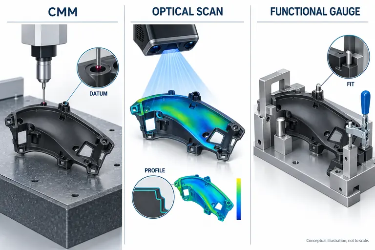
Metrology disputes often begin after tooling because the drawing names tolerances but not how a flexible, warped, textured plastic part will be aligned, restrained, sampled, or compared. CMM, optical scanning, and functional gauges can produce different answers because they solve different measurement problems.
Choose the method characteristic by characteristic. Use tactile CMM measurement for defined points and GD&T when probing and fixturing are suitable; optical scanning for dense surface, profile, warpage, and comparison data; and functional gauges for fast assembly-like acceptance. Create correlation and uncertainty evidence instead of declaring one technology universally best.
Define the measurand, part state, datum simulation, and decision
Start with the engineering decision: tool correction, first-article layout, process capability, production acceptance, assembly fit, or failure analysis. Then list each characteristic, tolerance, datum reference frame, surface accessibility, required output, sample frequency, and consequence of error.
Plastic state is part of the measurement definition. Record time after molding, temperature, humidity or conditioning, free versus restrained state, gate and flash preparation, and fixture method. A thin trim panel may change shape under its own weight or a probe. A conditioned polyamide may not match a dry-as-molded part. Without a controlled state, repeatability cannot rescue comparability.
Define datum simulation physically and digitally. A best-fit alignment can make a color map look balanced while ignoring the functional mounting scheme. Conversely, clamping every locator to nominal can hide natural distortion or impose stress not present in assembly. Use the drawing and functional stack to decide constraint, then document force, sequence, supports, and alignment algorithm.
ZEISS notes that first-article inspection may use a measurement plan, CAD or PMI and that optical or CT approaches can support shape and dimension analysis (ZEISS first-article inspection of plastic parts). This demonstrates method options, not guaranteed suitability or accuracy for every part.
Set an allowable measurement uncertainty or decision rule based on tolerance and risk. Accuracy claims require the specific machine, sensor, volume, environment, calibration, surface, setup, and procedure. Do not select from a marketing headline alone.
Use tactile CMMs where discrete geometry and traceable probing fit the part
A coordinate measuring machine is well suited to accessible points, holes, planes, cylinders, datum features, and GD&T evaluation when the part can be fixtured without unacceptable deformation. It supports programmed routines and auditable point data.
Probe access and contact force are constraints. Deep ribs, small slots, soft surfaces, and complex freeform geometry may be difficult. Stylus qualification, tip size, approach direction, scanning speed, and part deflection affect results. A few points may not represent a warped surface or a form error between points.
Design fixtures that support the agreed datum scheme while minimizing distortion. Use compliant or low-force probing where appropriate and verify with repeated setups. If a hole is flexible, measuring a few points with a spherical probe may not predict the fit of a real pin; a functional plug or assembly check can complement it.
CMMs are often strong for tooling correction because they report signed deviations at controlled features. Preserve the exact alignment and evaluation settings between T1 and later trials. A changed filter, point strategy, or datum construction can appear as part improvement or deterioration.
For capability studies, automate stable routines, identify cavities, and include operator/fixture variation in measurement-system analysis. Calibrate the equipment and verify the complete method with representative plastic parts—not only a rigid reference artifact.
Use optical scanning for full-field shape, while controlling surface and alignment
Optical scanners collect dense surface data and can reveal warpage, sink, profile variation, local mismatch, and tool-correction patterns that sparse points may miss. They are valuable for large freeform trim, comparative investigations, and virtual assembly.
Line of sight, surface reflectivity, translucency, deep features, texture, and target placement affect capture. Surface spray, if used, can add thickness and may be forbidden on appearance or customer parts. Multiple scans must be registered; unstable alignment can distort the result. State whether comparison uses functional datums, local features, or best fit.
ZEISS’s plastics guidance discusses full-field digitization and virtual assembly, while its warpage page emphasizes that clamped and unclamped states can produce different evaluations (ZEISS plastic-part design and scanning, ZEISS warpage on molded parts). Treat this as a reminder to define state, not as an endorsement of one brand.
Scanning does not automatically make every dimension accurate. Validate scale, calibration, exposure, polygon processing, smoothing, hole extraction, edge definition, and software settings. Compare selected features against a reference method. Retain raw data and processing recipe when the scan supports tool correction.
Use color maps carefully. Set meaningful limits and datum alignment, show direction and units, and avoid allowing a broad color scale to make a nonconforming part look green. The drawing remains the requirement; a visualization is evidence, not the specification.
Use functional gauges for fast decisions at the real interface
A functional gauge represents how features work together. It may simulate mating pins, panel holes, connector seats, gap/flush boundaries, clip installation, or a maximum-material virtual condition. It can provide rapid attribute acceptance on the production floor.
The gauge must reproduce the intended datum and assembly condition without becoming a substitute design. Define materials, wear surfaces, forces, sequence, go/no-go logic, replaceable details, master samples, calibration, and maintenance. Check that an operator cannot force a marginal part through and that the gauge does not damage appearance surfaces.
Functional gauges are less diagnostic than variable measurement. A failure shows that the assembly-like condition is not met, but not which dimension caused it. Pair them with CMM or scanning during development and when trends or failures need root-cause analysis.
| Need | Likely primary method | Complementary evidence |
|---|---|---|
| Hole, plane, datum and GD&T layout | Tactile CMM | Functional pin/gauge for fit |
| Freeform profile and warpage map | Optical scan | CMM checks on critical datums |
| Fast line-side assembly acceptance | Functional gauge | Variable data for capability and diagnosis |
| Tool correction across a surface | Optical scan with controlled alignment | Discrete CMM confirmation |
| Flexible feature under mating constraint | Functional fixture/gauge | Scan or CMM in defined restrained state |
Correlate methods before using them for release
Run the same representative parts through proposed methods, including good, marginal, and known-variable samples. Keep part state and datum strategy controlled. Compare results by feature, not only pass/fail.
Investigate systematic offsets: probe contact, scan surface treatment, fixture force, alignment, edge algorithm, temperature, timing, or operator technique. Decide which method is authoritative for each requirement and record conversion or guard-band rules only when technically justified.
Illustrative example—hypothetical, not an AutoMoldingPro project. A large trim panel passes a best-fit scan but fails vehicle gap. Reprocessing the scan with the functional datum scheme reveals locator-driven rotation. A CMM checks locator features, while a functional fixture confirms gap at assembly force. Tool correction targets the locator chain rather than averaging the show surface. The example demonstrates method correlation, not a universal correction process.
Perform measurement-system analysis appropriate to variable or attribute methods and actual use. Include fixtures, operators, cavities, range, and borderline parts. Revalidate after software, probe, fixture, gauge, or procedure changes. Maintain traceability of reports to part, revision, cavity, batch, condition, equipment, program, and operator.
Specify the metrology package in the RFQ
Provide CAD/PMI and released 2D drawing, datum scheme, plastic condition, restraint, appearance limits, sampling and capability expectations, customer report format, digital-data rules, and intended production frequency. Identify characteristics that need full-field evidence, variable values, or functional acceptance.
Ask the supplier to return a feature-to-method plan, fixture concept, equipment and software, access limitations, uncertainty or correlation evidence, gauge design and calibration plan, reporting format, subcontracted scope, and timing for T1, FAI, PPAP, and serial control.
Do not require scanning, CMM, and a gauge for every feature. Redundant measurement adds cost and can generate conflicting dispositions without improving decisions. Use each where its evidence is strongest and define the authority before samples arrive.
For a quotation review, send AutoMoldingPro the drawing, CAD, datum and conditioning rules, annual volume, critical interfaces, required reports, and customer-specific standards. A useful response should identify feasible methods, fixture assumptions, and evidence gaps rather than promise blanket precision.
Plan data ownership and revision control as well. Native CMM programs, scanner projects, alignment templates, gauge drawings, calibration records, and exported reports must identify software and part revisions. Decide whether the customer receives only reports or also raw point clouds and programs, and use formats that remain readable for the required retention period. Protect approved programs from casual editing and require a documented validation after changes. When the mold transfers to another plant, include fixtures, masters, offsets, training, and method-correlation samples; transferring only a PDF report does not transfer the measurement process.
Conclusion
Select CMM, optical scanning, and functional gauges by the characteristic and decision. Control part state and datum simulation, validate the complete measurement process, correlate overlapping methods, and define one authoritative acceptance route. The best metrology plan often combines methods without confusing their roles.