
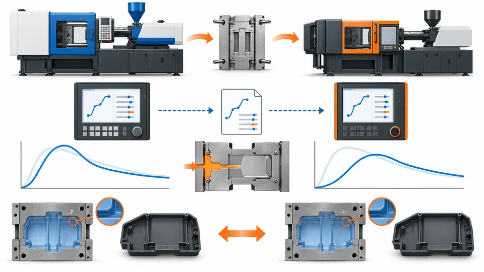
A recipe copied from one press can produce a different fill time, cushion, part weight or flash on another—even when machine brand and tonnage look similar. Controller units do not guarantee equal plastic pressure, volumetric flow, melt preparation, clamp behavior or thermal state.
Use the approved process as a response baseline, not a list of settings. Confirm receiving-machine capability, normalize shot volume and plastic pressure, reproduce material and mold thermal conditions, then match fill, transfer, cavity or hydraulic response and part evidence through a controlled study. Document machine-specific settings and complete the required customer revalidation.
Record the transfer in the table below. One row per item; a blank "receiving machine" cell means the transfer trial has not established that value yet.
| Item | Sending machine | Receiving machine |
|---|---|---|
| Screw diameter (mm) | [ ] | [ ] |
| Stroke for the same shot volume (mm) | [ ] | [ ] |
| Shot volume (cm³) | [ ] | [ ] |
| Intensification ratio | [ ] | [ ] |
| Plastic pressure at transfer (bar) | [ ] | [ ] |
| Maximum volumetric injection rate (cm³/s) | [ ] | [ ] |
| Mold and cavity-surface temperatures | [ ] | [ ] |
| Fill time (s) | [ ] | [ ] |
| Customer revalidation required | [ ] | [ ] |
Compare machine capability before mounting the mold
Platen size and clamp tonnage alone do not prove the receiving press can run the same process safely.
Review tie-bar spacing, daylight, ejector, nozzle, robot and utilities plus screw diameter, shot capacity, injection-rate and pressure capability, clamp response and controller functions.
The mold must fit physically, but the plasticizing unit also needs an appropriate shot utilization and residence condition. Compare maximum volumetric injection rate rather than only a percentage speed. Convert hydraulic to plastic pressure using the machine’s intensification where applicable.
Worked example — moving one shot to a bigger screw. Screw diameters and stroke below are assumed for illustration (not an AutoMoldingPro measurement); the method, not the numbers, is the deliverable. Shot volume is π/4 × screw diameter² × stroke. On the sending machine, a Ø45 mm screw at 60 mm stroke delivers π/4 × 45² × 60 = 95,426 mm³, or 95.4 cm³. On the receiving machine, a Ø55 mm screw delivers the same 95.4 cm³ at 95,426 ÷ (π/4 × 55²) = 40.2 mm of stroke. Copying the 60 mm stroke to the Ø55 mm screw instead would deliver π/4 × 55² × 60 = 142.5 cm³ — about 49% more material — and a different transfer position, cushion and fill. For pressure: a hydraulic pressure of 100 bar on a machine with a 12:1 intensification ratio is 100 × 12 = 1,200 bar of plastic pressure. The receiving machine’s ratio is different until proven otherwise, so a 100 bar setpoint on one press is not a 100 bar setpoint on the other. Normalize the volume and the plastic pressure first; the percentage speed and the stroke position follow from those, not the other way round.
Check whether velocity-to-pressure transfer, decompression, back pressure and profile controls are implemented equivalently. Ensure required mold-protection, cores, valve gates and hot-runner interfaces are available. A gap should be resolved before the transfer trial.
Build the review around machine datasheets, screw/plunger dimensions, pressure conversion, mold envelope and control/function comparison. The decision is whether the receiving press has physical and dynamic capability for the required process. A larger machine may offer pressure reserve but create poor shot utilization and residence; a smaller unit may be efficient yet lack rate or clamp margin.
Normalize volume, velocity and pressure
Millimeters of screw travel and percent velocity represent different material volume and flow on different screw diameters and controllers.
Translate shot positions into volume, commanded speed into volumetric flow where possible, and pressure into plastic pressure. Preserve limits separately from actual process response.
A larger screw delivers more volume per millimeter, so copying transfer position changes cavity fill. A controller’s 50 percent speed is not a cross-machine unit. Pressure setpoints may be limits during velocity control rather than achieved values. Calculate shot volume, cushion and decompression on the receiving geometry, then verify with short shots and actual fill time.The mold-transfer checklist lists every verification the transfer trial must cover before production resumes. RJG’s example shows matching machine templates did not match cavity pressure until the receiving process was adjusted. Keep all changes within machine and material limits.
The working record should contain normalized volume/flow/plastic-pressure worksheet, short shots, actual fill time and transfer/cushion records rather than a conclusion copied into email. Review the source, revision, units, sample selection and boundary conditions, then test whether the two setups deliver comparable material volume and fill response rather than similar display values. Normalized calculations provide a starting point; mechanical wear, controller tuning and check-ring behavior still require measured confirmation.
Match melt preparation and residence
Barrel setpoints do not ensure the same melt temperature, mixing, shear history or material residence on another plasticizing unit.
Compare screw design and diameter, shot utilization, cycle, screw speed, back pressure, recovery, decompression, residence and actual melt checks under safe approved methods.
Different screws create different shear and mixing. A small shot in a larger barrel may extend residence and degradation risk. The receiving press may recover faster with a different screw rpm but generate more shear. Match screw surface velocity or supplier-supported preparation metrics where relevant, not rpm alone. Confirm dryer and feed-throat conditions. Measure melt temperature using an appropriate method when needed and interpret its limitations. Observe recovery stability and check-ring repeatability through cushion or pressure behavior.
Ask the supplier to connect screw/barrel data, shot utilization, recovery profile, residence estimate, material preparation and melt evidence to the proposed part and production state. The evidence is sufficient only when material entering the cavity has a comparable and stable preparation state. Faster recovery protects cycle but can increase shear; lower screw speed may extend cycle and residence depending on the system.
Reproduce mold thermal and hydraulic conditions
Plant water, hoses, manifolds and controllers can change mold surface temperature and therefore fill, shrinkage and appearance.
Connect circuits to the verified diagram, compare coolant, flow, supply/return and actual mold surface response, and allow a defined thermal stabilization before judging transfer samples.
An identical controller setpoint can hide a different cavity temperature. Check blocked lines, series/parallel routing, hose loss and ambient conditions. Confirm hot-runner zone condition and valve-gate timing. Match cycle phase when measuring surface temperature. Use actual mold thermal-state mapping to keep measurement locations and stabilization criteria consistent between presses. Do not compensate for a cold mold by increasing melt heat or pressure without understanding the part impact. Link thermal readings to dimensions, warpage and appearance by cavity. Record receiving-cell hose and controller details in the machine-specific setup.
Use circuit hookup, flow and supply/return data, cavity-surface map, hot-runner status and stabilized part trend to challenge the preferred option. The release test is whether the mold reaches the thermal state associated with the approved process. Adjusting the controller may reproduce surface temperature, but equipment limits or poor flow must be corrected rather than hidden.
Match process response in a controlled sequence
Changing speed, transfer, packing and temperature together may produce acceptable parts without establishing an explainable equivalent process.
Use a staged study: establish fill-only behavior, transfer and cushion, pack/gate seal, cooling and cycle; compare cavity or machine response and parts at each gate.
Begin from normalized safe settings and produce short shots to compare flow progression. Match fill time and transfer state without pressure limiting. Then establish packing within the demonstrated gate-seal behavior and verify part weight by cavity. Confirm cooling and ejection. If cavity pressure sensing exists, compare the relevant curve features rather than forcing the old machine settings. Investigate check-ring leakage, nozzle loss or clamp response when the receiving press cannot reproduce output. Preserve the sequence and reasons for each change.
Before closing this point, reconcile staged setup study, short shots, fill/transfer/cushion, pressure or cavity response, weight and cycle data with the controlled product definition. The reviewer should be able to show that machine-specific settings create a comparable stable process response with no hidden limiting condition. Matching every curve point may be unnecessary, while matching only final dimensions can miss a fragile process; choose response metrics tied to product risk.
Complete product evidence and change approval
A technically centered receiving process still represents a changed production condition that may require customer approval.
Sample all active cavities across time, inspect defined characteristics and function, compare with the approved baseline, and follow the applicable change-notification and PPAP plan before release.
Review appearance, dimensions, weight, critical assembly and material/functional tests affected by machine and thermal change. Use the same measurement state and fixtures. Establish a process window where required rather than approving one nominal run. Document the new press, screw, controllers, utilities and machine-specific settings. Update control plans and reaction limits. Keep sending-press data and transfer samples for correlation. Do not call the move equivalent solely because Cpk or average dimensions appear similar.
Release from this stage should cite cavity/time sample plan, baseline comparison, functional results, process window and customer change disposition and explain why the receiving press is approved for production through required process and product evidence. Revalidation consumes time and samples, but protects against machine-specific effects that copied recipes cannot expose.
Cross-machine process transfer worksheet
Separate machine inputs from the process and product responses they create.
| Review line | Input or evidence | Decision or action |
|---|---|---|
| Capability | Fit, clamp, shot, rate, pressure and controls | Confirm feasible receiving press |
| Normalization | Volume, volumetric flow and plastic pressure | Set comparable starting point |
| Melt | Screw, recovery, residence, dryer and temperature | Match preparation |
| Mold thermal | Circuits, flow, coolant and surface map | Match tool state |
| Response | Fill, transfer, cushion, pressure, weight and cycle | Center receiving process |
| Approval | Cavity/product comparison and customer change scope | Release machine-specific setup |
Store the final settings under the receiving machine identity. The approved reference is the demonstrated process and part response, not a universal controller recipe.
Applying the method to a defined situation
A four-cavity tool moves from a hydraulic press to an electric press with a different screw diameter. Copying positions and percent speeds creates a shorter fill and flash. The team confirms machine capability, converts shot stroke to volume, establishes equivalent volumetric fill with short shots, checks melt preparation and restores the mold thermal map. Packing is rebuilt from gate-seal and cavity weight evidence. All cavities are then compared with the approved baseline under the required change submission before production release.
This illustrative scenario is not a customer case.
Questions for the supplier review
- Does the receiving press meet rate, pressure, shot and clamp requirements?
- How were screw positions and speeds normalized?
- Are actual pressure limits and achieved responses distinguished?
- Is melt residence and preparation comparable?
- Are coolant flow and cavity-surface temperatures reproduced?
- What product and customer evidence releases the new press?
Information to submit for a project-specific review
Provide sending and receiving machine specifications, screw sizes, full setup and actual process data, mold/utilities diagram, resin preparation, cavity results, approved samples and customer change requirements. Submit these inputs through the AutoMoldingPro request form. Mark unresolved points as assumptions so they can be priced and closed before tooling or production commitment.
Conclusion
Transfer the process response, not the display. Machine capability, normalized delivery, melt and mold thermal state, staged setup and product revalidation together establish a defensible receiving-press process.
References
- RJG machine-template transfer example
- RJG mold transfer application overview
- AutoMoldingPro mold transfer checklist
- RJG, "Finding Correlations to Part Quality with eDARTs" — the "Four Plastics Variables" (melt temperature, flow rate, pressure, cooling) to match across machines: https://rjginc.com/wp-content/uploads/2008/04/Finding_Correlations_to_Part_Quality_with_eDARTs.pdf