
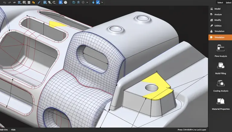
Large dashboard substrates combine long visible surfaces, local mounting features and interfaces to several assemblies. Uneven shrinkage can distort the panel, thick bosses can cause sink, and filling or cooling differences can alter appearance. If those relationships are left unresolved at tool release, correcting one feature can disturb another. Review the component architecture and its acceptance conditions before committing to the mold.
Injection molding can combine complex geometry and mounting features in dashboard substrates, cluster bezels, center-stack fascia, air-vent housings and display surrounds. The substrate, visible trim and soft-touch layers need separate material and process decisions; a complete dashboard is not necessarily one molding. Candidate families include modified or reinforced PP for panel structures and PC/ABS for selected interior components.12 Success depends on wall-thickness control, gate placement, cooling design, and validation of the exact material and finish.
The following review connects material, process, geometry, tooling and validation decisions before mold approval, including the trade-offs between integrating features and using separate components.
Why Is Injection Molding the Preferred Process for Dashboard Panels?
Some teams assume any large plastic part can be molded the same way. Then they discover that a one-meter dashboard substrate behaves nothing like a small clip. The part warps, the surface shows sink and gloss variation, and the mold costs far more than expected. Choosing the right process early avoids these late-stage shocks.
Injection molding is a useful candidate when the component needs complex geometry, integrated features and repeatable production. Its economic case depends on lifetime demand, tooling, cycle, finish, scrap and assembly scope. For suitable geometries, gas assistance, sequential valve gating and two-shot molding can address thick sections, flow-front control or compatible hard/soft combinations. Select the variant for the component rather than assuming the entire dashboard needs the same process.
Where injection molding earns its cost
Compare tooling investment and recurring production cost over the program’s actual demand and design life; there is no universal volume at which one dashboard route becomes cheapest. A dashboard substrate can integrate the following into one molding:
- Instrument-cluster and display openings
- Air-vent apertures
- Fastener bosses and locating pins
- Snap fits, clips, and wire-routing channels
- Brackets for HVAC or electronic modules
Process variants that matter for dashboards
- Gas-assisted injection molding can hollow suitable thick sections to reduce material and address sink. Verify the channel geometry, remaining wall and structural performance rather than assuming hollowing preserves stiffness.
- Sequential valve gating controls when melt enters through each gate. With an appropriate layout and timing, it can reduce or relocate weld lines between gates. Flow that divides and rejoins around an opening can still form a weld line; verify location and appearance on the actual panel.3
- Two-shot and overmolding can combine compatible soft and rigid materials. Confirm the bond or mechanical retention, thermal compatibility and tool sequence; a separately formed skin and foam-backed panel uses a different assembly route.
- In-mold decoration (IMD) applies a decorative or scratch-resistant film during molding, reducing secondary painting.
Decide the process strategy during DFM, before cutting steel. Check whether the proposed route can meet the component’s flow length, appearance zones, attachment features and layer interfaces.
Which Materials Are Best for Automotive Dashboard Components?
Material selection often gets rushed. A team copies a resin from a previous project without checking cabin temperature, emissions limits, or the OEM approved-material list. The mold then produces parts that warp under summer heat, fail odor testing, or cannot meet the appearance spec. This is one of the most costly mistakes in dashboard programs.
Modified and reinforced PP grades are available for dashboard panels and carriers; PC/ABS grades are candidates for interior components needing a balance of appearance, impact and dimensional control.12 The family name does not rank every grade. Filler, impact modification, color, surface treatment and the acceptance state change the result. Use the approved grade and customer requirements to compare exact interior resin grades before selecting tooling assumptions.
Material comparison for dashboard applications
Use this table to screen candidates, not to approve a grade or assign universal performance scores.
| Requirement | Modified or filled PP | PC/ABS | Glass-filled PP or PA |
|---|---|---|---|
| Density / weight | Low-density starting family; filler and the required wall section change part mass | Compare the actual grade density and wall section with the PP design | Reinforcement changes density but may permit a stiffer, thinner section; compare finished-part mass |
| Impact resistance | Select the impact-modifier/filler balance at the required temperature | Specify the blend and impact grade, including cold-condition requirements | Check loading relative to fibers and weld lines; PA moisture state also matters |
| Heat / thermal stability | Verify creep and stiffness under the actual cabin load and temperature history | Compare grade-specific thermal data; a short-term test temperature is not a service limit | Review reinforcement, polymer and heat stabilization together; do not transfer a PA result to PP |
| Dimensional stability | Check shrinkage, filler and the gate/cooling pattern on the long panel | Low-shrinkage grades can help; molding stress, heat and assembly restraint still need checking | Fiber orientation makes movement directional; PA also requires a defined moisture/conditioning state |
| Surface appearance | Use a surface-qualified grade and trial the specified grain, gloss and color | Match the grade to molded finish, paint or metallization requirements | Check fiber read-through and the surface requirement before assigning a visible application |
| Cost basis | Quote exact compound, scrap and any finish operation | Include drying, finish and the selected grade in the comparison | Include reinforcement, tool wear and handling/conditioning requirements |
| Candidate use | Panel substrate, carrier or trim where grade and appearance are suitable | Interior fascia, bezel or housing where the approved grade meets its interfaces | Structural carriers, brackets or mounts after load and environmental validation |
Practical selection criteria
Check these points before tooling:
- Peak cabin temperature exposure, especially near glass and vents
- Impact and head-impact safety requirements for the location
- Odor, fogging, and volatile-emission limits
- Scratch and mar resistance for touch surfaces
- Recyclability and any bio-based or recycled-content targets
- The OEM’s approved-material list and customer-specific requirements
Recycled or renewable-feedstock grades may be candidates where the customer permits them. Flow behavior, color consistency, and mechanical performance must be revalidated. Never assume a recycled grade drops in without testing. Always verify the final choice against the approved drawing, the material technical datasheet, and the customer-specific requirements.
How Do You Control Warpage and Cosmetic Defects on Large Dashboard Panels?
A large panel can distort through uneven shrinkage, orientation, cooling or ejection. Establish a repeatable measurement state before deciding whether geometry or processing caused the mismatch. Sink, weld lines and gloss variation also need the customer’s appearance zones and viewing conditions; their acceptability cannot be judged from a generic Class-A label. How appearance zones, masters and viewing conditions are defined is covered in the cosmetic-acceptance guide: Cosmetic Acceptance for Automotive Trim: Color, Gloss and Grain.
Wall distribution, gate placement, packing and cooling must be reviewed together. Size ribs from the selected resin’s design guidance, structural load and show-surface relationship; a remembered rib-to-wall ratio does not prove freedom from sink. Identify allowable gate vestiges and use simulation to assess fill, weld-line location and warpage before tool release. Correlate those predictions with molded parts and the agreed measurement setup. The warpage guide works through thin-wall interior panels — gate and cooling balance, free-state vs installed measurement, and what a scan can hide: Warpage in Thin-Wall Automotive Interior Panels.
Design rules that reduce warpage
- Maintain relatively uniform nominal wall thickness across the part.
- Core out thick solid sections instead of adding mass.
- Use generous radii at corners and transitions.
- Add ribs for stiffness rather than increasing wall thickness.
- Balance the filling pattern so no region shrinks dramatically differently.
Common cosmetic defects and corrective actions
| Defect | Likely cause | Typical correction |
|---|---|---|
| Warpage | Uneven wall, unbalanced fill, uneven cooling | Improve wall uniformity, rebalance gates, optimize cooling |
| Sink marks | Thick bosses or ribs, low packing | Core out thick sections, reduce rib thickness, improve packing |
| Weld lines | Flow fronts meeting between gates or rejoining around openings | Review gate location/timing and venting for the actual flow path; verify the resulting line against appearance and functional limits |
| Gloss/texture variation | Uneven cooling, unstable process | Balance cooling, stabilize conditions, refinish inserts |
| Ejection whitening | Low draft, high ejector load | Increase draft, improve cooling, relocate ejectors |
The role of cooling design
Conformal cooling is an option where conventional channels cannot control a local thermal problem. Compare the proposed thermal balance with available flow, pressure loss, channel cleaning, repair access and tool cost. Any claimed cycle or warpage improvement needs simulation and trial evidence for that tool. Discuss the cooling strategy during mold design, and record circuit flow and temperature conditions during the trial.
What Tooling and Draft Requirements Apply to Dashboard Molds?
Dashboard tooling is large, expensive, and unforgiving of design mistakes. Teams sometimes approve a mold quotation based on price alone, then discover the tool lacks proper cooling, adequate venting, or replaceable inserts in wear areas. Fixing these problems after cutting steel is slow and costly.
Large substrate molds may need multiple hot-runner or valve gates, distributed cooling and substantial ejection support; a smaller bezel may justify a different arrangement. Define draft for each pull surface from the resin, depth, texture and release method rather than approving a universal angle. Place ejectors in agreed non-cosmetic areas with adequate support, then verify that release does not whiten or deform the part.
Tooling options to assess before approval
- Hot-runner or valve-gated injection system suited to the flow length
- Multiple gates positioned for balanced filling
- Distributed cooling circuits, including conformal cooling where needed
- Replaceable cavity inserts in high-wear or cosmetic areas
- Hydraulic or servo slides for undercuts and apertures
- Robust ejector layout on non-visible surfaces
- Documented mold steel, cavity count, and expected mold life
Machine selection
The required clamp force depends on projected part area, material, gate strategy, and cavity count, not part weight alone. A large substrate needs a much larger machine than a small bezel. Use the fill/pressure analysis and the machine manufacturer’s performance data, then check mold envelope, shot capacity, injection rate and pressure, ejection and cell access. Inadequate clamp force can permit flash; insufficient injection capability can prevent filling. A larger press alone does not resolve those separate constraints.
A modular versus integrated decision
Integrating every feature into one large molding increases mold complexity, service difficulty, and dimensional risk. A modular architecture, such as a PP substrate plus a separate PC/ABS bezel, can be preferable when parts need different materials, finishes, or tolerances; compare the resulting joints, assembly operations and interface risks. Do not chase part-count reduction at the expense of moldability and quality.
What Quality and Compliance Requirements Apply to Dashboard Parts?
Dashboard components carry safety and appearance responsibilities that many teams underestimate. Passing dimensional inspection is not enough. If the material fails flammability, emissions, or heat-aging tests during validation, the entire program stalls while you re-source or re-qualify material.
Dashboard validation goes well beyond dimensions. The program’s validation plan may require dimensional and appearance approval, impact and heat aging, thermal cycling, scratch and chemical resistance, odor/emissions, clip retention and flammability evidence. The production control plan then specifies the recurring checks, frequency and reaction plan needed to maintain the approved condition; it need not repeat every validation test on every lot.
For applicable U.S. vehicle interior components, FMVSS No. 302 sets a burn-rate limit of 102 mm/min under its prescribed method. Scope, sampling and the 13 mm rule are covered in the FMVSS 302 guide: Automotive Interior Flammability — FMVSS 302 Scope and Samples. Its scope identifies component portions within 13 mm of the occupant-compartment air space, and it distinguishes separately tested materials from layers bonded at every contact point and tested as a composite.4 Define the actual skin, foam, substrate and bonding construction with the responsible customer and test laboratory rather than treating a resin-family label as compliance evidence.
Validation checklist before mass production
- First-article dimensional report against the approved drawing
- CMM or 3D-scan results for critical dimensions and GD&T
- Color, gloss, grain, and appearance approval
- Impact, heat-aging, thermal-cycling, and humidity results
- Scratch, abrasion, and chemical-resistance data
- Odor and volatile-emission testing per OEM requirement
- Flammability testing per the applicable specification
- Process-capability study on critical characteristics
APQP and PPAP context
Where the customer requires Advanced Product Quality Planning (APQP), coordinate design-for-manufacturing review, flow analysis, tooling, sampling, dimensional and appearance approval, capability evidence and the Production Part Approval Process (PPAP) against the agreed program gates. These activities can overlap and iterate; a T1 or T2 trial label does not itself authorize the next gate. PFMEA, the control plan, MSA, and SPC support consistent production. These are quality-planning tools, not product certifications. The exact submission level and required tests depend on customer-specific requirements, so confirm them with your OEM before starting validation.
A practical component strategy
One candidate architecture is a qualified modified-PP substrate with a separate PC/ABS bezel, defined bosses and snap features, and a separately specified soft-touch layer where required. Compare it with a more integrated option using the actual material, finish, attachment, tolerance and assembly requirements. Neither the material pairing nor the soft-touch construction is a universal dashboard specification.
Conclusion
Successful dashboard molding depends on decisions made before steel is cut: right material for the temperature and appearance spec, uniform wall thickness, balanced gating, proper cooling, and a realistic modular strategy. To request a dashboard DFM review, provide the STEP model and released drawing, component/layer layout, exact resin or approved candidates, appearance zones, assembly interfaces, annual demand and customer validation requirements. Identify unresolved material or test decisions before approving tooling or production.
Dashboard DFM input checklist — copy this into the RFQ
Send every row below with the RFQ. A missing row is not a minor omission: the molder prices and tools on assumptions, and each assumption is a late change waiting to happen.
| Input | What to send | What breaks if it is missing |
|---|---|---|
| Part definition | STEP model and released drawing, component/layer layout | Tooling quoted on the wrong geometry; layer interfaces missed |
| Resin | Exact resin grade, or the approved candidate list | Tool steel, shrinkage and gate design set on the wrong material |
| Appearance zones | Zoned drawing: visible, touch, hidden; grain, gloss and color masters | Sink, weld lines or gate marks judged against the wrong zone |
| Wall and feature map | Nominal wall, rib/boss sections, clip and mounting features | Sink opposite thick features; clips that cannot be reached or retained |
| Gate and weld-line rules | Allowed gate positions and vestige limits; weld lines that must stay out of visible zones | Weld line across a Class-A surface found at first trial |
| Cooling and warpage | Gate/cooling concept, free-state limits, measurement state (free vs installed) | Warpage blamed on process when the datum scheme was never agreed |
| Flammability | Applicable specification (e.g. FMVSS 302 scope) and the actual skin/foam/substrate construction | Material passes as a resin label but fails as a bonded construction |
| Validation scope | Dimensional and appearance approval, impact and heat aging, thermal cycling, odor/emissions, clip retention | Validation stalls at the first test the resin was never checked against |
| Assembly interfaces | Mating parts, fasteners, seals, harnesses, installation direction and force limits | A panel that fits its own drawing but not the vehicle |
| Demand and life | Annual demand, program life, service horizon | Tooling sized for the wrong volume; cavity count and mold life mismatched |
-
Borealis, Mobility Interior Solutions — panel/carrier applications and differences among PP-based grades. ↩ ↩
-
Covestro, Engineering Thermoplastics — Bayblend grade families and automotive applications; typical data require application-specific verification. ↩ ↩
-
Autodesk Moldflow, Valve gate controllers — sequential opening and the flow fronts between gates. ↩
-
49 CFR 571.302, Flammability of interior materials — component scope, material-layer treatment and prescribed test requirements. ↩