
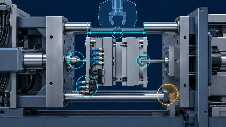
Conceptual illustration; not to scale.
An export mold can arrive with excellent trial parts and still be unusable on the customer’s press. Tie-bar clearance, mold height, platen pattern, locating ring, nozzle reach, ejector interface, electrical standards, water fittings, robot access, or controller compatibility may differ. Solving those conflicts after shipment turns a tooling project into an unplanned machine-conversion project.
Confirm fit with a signed mold-to-machine interface review before mold design release and repeat it against the as-built tool before shipment. Compare verified machine data with the complete mold envelope, clamping, injection unit, ejection, utilities, hot runner, actuation, handling, guarding, and automation. A tonnage match alone does not establish compatibility, and a machine model name is not a substitute for destination-specific measurements and options.
Collect destination-machine data that can be verified
Generic catalogue data is useful for screening, but the installed press may have option packages, platen inserts, a different screw, added guarding, robot hardware, worn interfaces, local connectors, or plant modifications. Obtain both manufacturer data and destination-plant confirmation.
Record manufacturer, model, serial or asset number, controller, year or configuration where relevant, clamp type, tie-bar spacing, platen dimensions and thickness, mounting-hole and T-slot details, minimum and maximum mold height, opening stroke, daylight, moving-platen stroke, ejector pattern and stroke, and permitted mold mass. Request clear photographs and a dimensioned platen/interface drawing. Confirm whether magnetic platens, quick mold change, insulation, support rails, or adapters reduce usable space.
For the injection unit, record screw diameter, maximum shot volume or mass under the manufacturer’s stated basis, maximum injection pressure, injection rate, plasticizing capacity, nozzle radius, orifice, tip style, protrusion and stroke, locating-ring recess, and carriage force or contact arrangement. Resin density and processing conditions affect usable shot capacity; avoid converting catalogue values without stating assumptions.
Collect available electrical supply, controller connectors, thermocouple type, heater voltage and current limits, hot-runner zones, valve-gate control, hydraulic and pneumatic pressure/flow, cooling-water temperature/flow/pressure, fitting standards, drain or leak-management needs, vacuum, compressed air, data interfaces, robot and conveyor envelope, crane and lifting limits, and plant safety requirements. Have the destination engineer approve the completed data sheet.
Mark each value as manufacturer data, plant measurement, calculated requirement, or open assumption. That provenance tells the tool designer which interfaces still need physical confirmation.
Verify the mechanical envelope and clamping interface
The mold must pass between the tie bars or enter through the machine’s intended loading path, sit on the platen, close within the mold-height range, open far enough for part and runner removal, and remain within load and support limits. Check the whole installation sequence, not only the final closed position.
Compare mold width and height, lifting brackets, protruding cylinders, hoses, connectors, terminal boxes, hot-runner plugs, insulation plates, feet, and storage blocks with the loading envelope. Include required rotation and crane hook approach. A mold body may fit while a side-mounted connector cannot pass a tie bar.
Confirm mold thickness against minimum and maximum mold height and calculate daylight at full opening. Required opening includes part depth, core or slide movements, runner extraction, robot gripper, release path, and a safety margin defined by the project. Verify moving-platen stroke and any sequence needed for hydraulic cores before ejection.
Map clamp slots, bolt holes, T-slots, quick-clamp or magnetic-platen zones. State bolt grade, engagement, clamp hardware, torque method, and any spacer or support plate according to the machine, plant, and tooling design. Do not drill or modify an as-built mold during installation without engineering review. Check mold mass, permitted moving-half mass, center of gravity, support requirements, and machine/platen limits with the manufacturer or destination plant.
Match locating ring, nozzle, and injection capacity
The injection unit must center, seal, reach, and deliver the required melt without operating at an unsuitable extreme. Misalignment or incompatible radii can leak, damage the sprue bushing, restrict flow, or load the mold incorrectly.
Confirm locating-ring outside diameter, thickness, recess and fit with the fixed platen. Compare nozzle-tip radius with the sprue-bushing or hot-runner inlet radius and verify orifice diameters, seating geometry, protrusion, carriage stroke, contact force, and thermal expansion. Draw the interface section with datums and tolerances. Do not rely on nominal phrases such as “standard EU nozzle”; use the actual machine and mold dimensions.
For shot capacity, calculate molded-part mass across all active cavities plus runner and an allowance based on the selected process strategy. Compare this with usable barrel capacity for the actual resin and screw. Also consider residence time, recovery time, injection rate, pressure demand, screw stroke use, and material sensitivity. A shot may fit the catalogue maximum while producing poor residence time or insufficient rate and pressure margin.
Review clamp force from projected area and expected cavity pressure using a documented engineering basis. The final process must avoid flash and protect the machine and tool; simply choosing the highest available clamp setting can hide imbalance or support problems. Confirm that the destination machine can reproduce the required fill rate and pressure within its actual performance envelope.
Record the required process margin and who approved it. A combination that operates only at a machine limit deserves a risk decision even if one trial succeeds.
Confirm ejection, cores, hot runner, and sensors
Moving functions frequently cause late export-tool changes because mechanical fit was reviewed without sequence and control. Build an interface table for every actuator and feedback signal.
For ejection, compare machine ejector pattern, rod diameter and thread, center and auxiliary locations, stroke, force, retraction confirmation, return pins, spring return, and coupling method. Check that the molded part and runner clear the tool at the available stroke. If the machine uses a European-style coupling or a local adapter, document the exact component and retained engagement.
For hydraulic cores, list cylinders, required pressure and flow, port and hose specification, sequence relative to mold opening/ejection, locking method, end-position sensors, and fail-safe condition. For pneumatics, identify clean-air requirements, valves, pressure, exhaust, and monitoring. Ensure hoses do not enter pinch zones or prevent guarding.
For hot runners, map each heater and thermocouple zone, voltage, wattage/current, thermocouple type, connector pinout, grounding, insulation-resistance test, controller capacity, valve-gate channels, and alarm/interlock behavior. Use the installed hot-runner supplier’s manual. A physically matching plug does not prove correct wiring.
Create an I/O list for mold-protection sensors, pressure or temperature transducers, ejector return, slide position, part detection, robot permissives, and auxiliary control. Confirm signal type, voltage, connector, logic state, cable shielding, and ownership of adapters. Test the complete sequence during destination acceptance.
Simulate safe failure conditions where the approved commissioning plan permits it, such as missing return confirmation or an unplugged sensor. Verify that the sequence stops before collision rather than only checking the normal cycle.
Design cooling and utility connections for the receiving plant
Cooling performance depends on circuit flow and temperature, not the color of a hose. An export mold should arrive with labeled circuits and connection requirements that the receiving plant can reproduce.
Provide a cooling schematic with circuit numbers, inlet/outlet, channel or component served, fitting thread and size, hose requirement, allowed pressure, target supply condition, and measured flow or restriction from the acceptance trial. Check manifolds, serial versus parallel routing, moving connections, leak detection, drain-down, corrosion protection, and clearance from clamps and guarding.
If the destination uses different quick-connect standards, fit approved adapters or supply a controlled conversion kit before shipment. Avoid stacking temporary adapters that reduce flow or create unsupported loads. Verify sealing material compatibility with the intended water quality, temperature, glycol or treatment system where applicable.
Do the same for hydraulic oil, compressed air, vacuum, electrical power, data and lubrication. Identify responsibility for controllers, temperature-control units, dryers, loaders, granulators, robots, conveyors, pressure/flow regulators, and hoses. A tooling quotation should state whether auxiliaries are included, interface-ready, or supplied by the destination.
Use a mold-to-machine compatibility matrix
Complete and approve this matrix before design freeze, update it after as-built inspection, and close every exception before shipping.
| Interface | Destination-machine evidence | Mold requirement | Verification | Status/owner |
|---|---|---|---|---|
| Loading and tie bars | Measured clearances and loading path | Full envelope including attachments | 3D/2D interference review | Open / pass |
| Mold height and opening | Min/max height, stroke, daylight | Closed height and required release opening | Calculation and dry sequence | Open / pass |
| Clamping and support | Platen holes/T-slots, limits | Slots, bolts, plates, mass and center of gravity | Drawing and installation plan | Open / pass |
| Locating/nozzle | Ring, recess, nozzle geometry and reach | Locating ring and inlet section | Dimensioned interface section | Open / pass |
| Injection performance | Screw, shot, rate and pressure | Resin, shot, fill and pressure need | Engineering review and trial | Open / pass |
| Ejection/cores | Pattern, stroke, force, hydraulic/pneumatic supply | Actuators and sequence | Dry cycle with I/O | Open / pass |
| Hot runner/electrical | Supply, zones, connectors, controller | Loads, pinout, sensors and grounding | Electrical test and controlled heat | Open / pass |
| Cooling/utilities | Available temperature, flow, pressure and fittings | Circuit map and requirements | Flow/leak test | Open / pass |
| Automation/safety | Robot, guarding and plant rules | Part/runner path and permissives | Cell layout and risk review | Open / pass |
Attach drawing references, photographs, calculations, approved adapters, and revision dates. An unchecked row is an open project risk, not a presumed match.
Illustrative example: a mold that fits the clamp but not the cell
This illustrative example is not a customer installation. An export mold is designed for a destination press whose catalogue clamp size appears suitable. During final interface review, the mold envelope fits between tie bars and its thickness is within range. The initial checklist would call it compatible.
The dimensioned review finds three remaining conflicts. A side hydraulic cylinder collides with the fixed guard during loading, the nozzle reach is insufficient after an added insulation plate, and the destination controller has fewer valve-gate channels than the mold design. None is resolved by increasing tonnage.
Before shipment, engineering repositions the approved cylinder package without changing the product-forming function, revises the support and insulation arrangement while rechecking mold height and heat transfer, and agrees a compatible valve-gate controller and connector map. The changes are reflected in as-built drawings and tested during the source acceptance trial.
At the destination, the team verifies lifting, clamp, nozzle contact, utilities, dry sequence, hot-runner zones, and robot path before introducing material. Compatibility is accepted from the complete interface record and physical checks—not from the machine model printed on the purchase order.
Information to send an export mold supplier
- destination press manufacturer, exact model/configuration, asset contact, interface drawings and photographs;
- tie-bar, platen, mold-height, stroke, daylight, mass, support and loading limits;
- screw, barrel, injection rate/pressure, nozzle, locating-ring and carriage details;
- ejector pattern, coupling, stroke, force and sequence;
- electrical, heater, thermocouple, sensor, controller and connector standards;
- hydraulic, pneumatic, cooling, vacuum and fitting requirements;
- robot, gripper, conveyor, guarding, crane, mold cart and maintenance-clearance information;
- resin, shot mass, cavities, runner, target cycle, part release path and critical process needs;
- plant safety, documentation, language, certification and acceptance requirements.
Require written confirmation of uncertainties. If the machine sheet omits an interface, measure it at the destination rather than letting the toolmaker assume.
Conclusion
Approve export-mold fit from a complete, destination-verified interface matrix and an as-built recheck. Send AutoMoldingPro the part and resin data, mold concept, exact press configuration, platen/nozzle/ejector drawings, utility standards, controller details, automation envelope, and acceptance requirements before tool design release.