
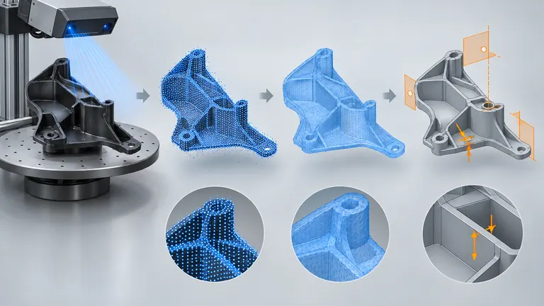
Conceptual illustration; not to scale.
Home › Blog › Can an Existing Automotive Plastic Part Be Reproduced Without a 3D CAD File?
Automotive sourcing and manufacturing decision guide
A physical part feels like a complete specification because every surface is visible or scannable. In reality, it represents one molded, aged, loaded, and possibly damaged condition. Copying that surface can preserve wear and deformation while losing nominal dimensions, tolerances, material, hidden interfaces, and the authority needed to approve the replacement.
Reconstruction is feasible only when the requesting party has confirmed authority and a design owner can approve a new baseline. Assess several samples and mating interfaces where possible, combine scan data with controlled measurement, rebuild editable CAD around functional datums, define drawings, material, appearance, and tolerances, perform DFM, and validate production-intent parts against the newly approved specification—not merely against one old sample.
The first decision is evidence sufficiency. More uncertain inputs demand more measurement, engineering judgment, validation, and explicit residual-risk acceptance before tooling.
In This Guide
- Confirm Design and Reproduction Authorization First
- Assess Whether the Sample Represents the Intended Nominal Part
- Decision Table Based on Available Inputs
- Turn Measurements Into a Controlled, Editable Production Definition
- Confirm Material, Color and Critical Interfaces Separately
- Validate the Reproduced Part Against the New Approved Baseline
Confirm Design and Reproduction Authorization First
Why this matters: A technically scannable part may still lack reproduction rights, design responsibility, marking decisions, or an authority able to approve reconstructed data. Tooling without that chain can produce an unusable asset.
Before measurement or data sharing, identify design and tool ownership, intended program and use, confidentiality, permission to reproduce and modify, controlled markings, safety responsibility, and the person or organization authorized to release the new definition.
Identify the design owner, tool owner, program/customer and intended use. Obtain written confirmation that the requesting party can reproduce, modify and supply the part and can share the physical sample, drawings and related specifications with the selected supplier.
Treat markings, logos, part numbers and embedded supplier identifiers as controlled information. Do not remove or copy them by default. The design authority must decide which marks are required, prohibited or replaced in the new definition.
If authorization, safety responsibility or specification ownership is unclear, stop before scanning or tooling. This article is an engineering workflow, not legal advice.
Use an authorization-and-governance checklist. Record the requesting legal entity, part number and program, reason for reconstruction, source and permitted use of samples and files, design owner, tool owner, trademark or supplier markings, data-sharing boundary, change authority, validation authority, and intended manufacturing and sales regions. Confirm whether the task is service support, an approved second source, recovery after tool loss, transfer support, or redesign. These scenarios may require different commercial and approval records even when the geometry is identical.
Do not ask a manufacturing supplier to decide intellectual-property or product-safety ownership. The responsible customer or design authority must provide that direction, and appropriate legal review belongs with qualified counsel when rights are uncertain. Illustrative stop condition: purchasing supplies one branded used part but cannot identify the drawing owner or who may authorize copied markings. The correct next step is to resolve ownership and release responsibility, not to remove the logo from a scan and proceed. Preserve the decision record with the technical project files.
Authority
- Design/reproduction permission
- Tool and data ownership
- Trademark/marking disposition
- Approval and change authority
Use case
- Service replacement
- Second-source/continuity
- Tool-transfer recovery
- Redesign or interface study
Release path
- Target customer/program
- Required validation/PPAP route
- Safety/regulatory classification
- Who can approve reconstructed CAD
Assess Whether the Sample Represents the Intended Nominal Part
Why this matters: One sample includes molding variation, shrinkage, residual stress, assembly load, service aging, wear, repair, and storage deformation. Treating all measured surfaces as nominal can encode defects into the new CAD.
Document each sample’s history and condition, compare multiple parts and mating components, and distinguish repeatable design geometry from damage or manufacturing variation. Use complementary measurement methods for inaccessible or critical features.
A used sample may be worn, heat-aged, chemically exposed, clipped under load, repaired or warped by service. A warehouse sample may still contain molding shrinkage, residual stress or packaging deformation. Record condition before treating any surface as nominal.
Use more than one authorized sample when possible: unused reference, parts from different cavities/lots, mating components and an assembly-level example. Compare repeatable geometry to isolate damage and manufacturing variation.
Document missing or inaccessible features. Optical scanning may not capture deep holes, glossy/transparent surfaces, hidden snaps, texture depth or internal passages without additional preparation or computed tomography. Combine scanning with calibrated contact measurement, sectioning only when authorized, and functional interface data.
Create a sample-condition report before cleaning, cutting, coating, or fixturing the part. Photograph all sides with an ID and scale; note source, claimed age, cavity or lot marks, service location, temperature or chemical exposure, load state, repairs, fractures, abrasion, creep, discoloration, contamination, and missing features. Measure free-state deformation and, where relevant, the installed condition. An unused service part can be valuable, but packaging and long storage may also influence thin or stressed geometry.
Compare a population rather than averaging blindly. Align parts on functional datums or mating features, then map common geometry and outliers. Differences may reflect cavities, tool wear, process variation, post-mold conditioning, or service damage. Use optical or structured-light scanning for accessible surfaces, calibrated contact methods for critical datums and bores, and authorized sectioning or computed tomography only when justified. Record measurement uncertainty and surface preparation. Reflective spray, target placement, and mesh smoothing can alter the apparent surface, so keep raw data and the processing history.
Decision Table Based on Available Inputs
Why this matters: Teams often treat released drawings, old CAD, clean samples, worn samples, and an STL mesh as equivalent starting points. They provide very different evidence about nominal geometry, tolerance, intent, and approval.
Classify the available inputs before quoting tooling. Select the best-supported route, list missing decisions and residual risks, and stop if authorization or approval responsibility is absent. Lower-evidence routes need a larger validation plan.
Use the best available row; do not pretend that a lower-evidence route produces the same confidence as released CAD and specifications.
Use the decision table as an intake gate. Mark every available artifact, owner, revision confidence, condition, units, coordinate system, and permitted use. Released 2D data can control critical dimensions even when 3D is missing. Old CAD may reveal design intent but must be reconciled to later drawings and samples. Several parts show variation but do not establish the target tolerance. A mesh is measured reference geometry, not automatically a watertight, editable, dimensioned production model. Mating components and assembly data often carry more functional information than an isolated sample.
Illustrative scenario: the team has a worn in-service clip, an old undated STEP file, and a current mating panel drawing. The table classifies the old CAD as a hypothesis, the clip as condition evidence, and the panel drawing as a controlled interface. Engineering compares all three, requests unused samples and material history, and records which geometry must be newly specified. Tool quotation remains provisional until the design authority approves the reconstructed interface and validation plan. This is more honest than claiming that scan accuracy alone closes the missing revision history.
| Available evidence | Decision, next work and residual risk |
|---|---|
| Released 2D + good samples + mating data | Decision: feasible assessment. Next work: rebuild 3D around controlled dimensions, verify interfaces, define missing tolerances/material, compare CAD to samples. Residual risk: undocumented geometry/design intent. |
| Old 3D/2D + worn sample | Decision: reconcile before tooling. Next work: revision audit, wear/warpage map, authority disposition, reconstruct only approved differences. Residual risk: mixing revisions or copying wear. |
| Several samples, no drawings | Decision: possible concept reconstruction, not automatic release. Next work: scan/measure population, infer nominal geometry, create datum/tolerance proposal, functional validation plan. Residual risk: unknown nominal and acceptance limits. |
| One used sample only | Decision: high-uncertainty feasibility study. Next work: condition report, mating/functional inputs, material analysis and additional evidence request. Residual risk: wear, shrinkage, damage and no variation evidence. |
| Mesh/STL only | Decision: reference geometry only. Next work: verify scale/coordinate/scan uncertainty; rebuild editable surfaces/features; define drawing and tolerances. Residual risk: faceted geometry and absent design intent. |
| No authorization or approval authority | Decision: stop. Next work: resolve rights, ownership, safety and release responsibility. Residual risk: unauthorized reproduction and unusable validation path. |
Turn Measurements Into a Controlled, Editable Production Definition
Why this matters: Automatic mesh conversion can create a faceted or over-fitted model that is difficult to edit, dimension, tool, and inspect. A close surface match does not restore design intent or nominal tolerance.
Establish functional datums, reconstruct editable features and surfaces, compare them with raw measurements, document intentional nominalization, and release a drawing or specification with tolerances, material, finish, and validation requirements.
Autodesk’s official reverse-engineering workflow explains that a scan produces point-cloud/mesh data and that accurate editable models normally require manual or semi-manual remodeling. A scan mesh records the measured surface of one physical condition; it does not restore nominal dimensions, tolerances, hidden design intent or material.
Hexagon’s Geomagic Design X overview distinguishes mesh/point-cloud processing, creation of editable parametric solid models and comparison of reconstructed CAD back to scan data. Use that comparison as one check—not as proof that the nominal design is correct.
Establish coordinate system and functional datums from the assembly, not just from the scanner’s best fit. Reconstruct primary planes, axes, holes, clips, ribs, walls, shutoffs and freeform surfaces with design intent. Apply symmetry or regularization only when authorized.
Create a 2D drawing or controlled specification for dimensions, tolerances, material, finish, appearance zones, markings and validation. A production supplier cannot inspect “match the sample” consistently when the characteristic and acceptance method are undefined.
Plan capture around the required decisions. Define scanner setup, target accuracy, reference artifacts, contact-measurement points, inaccessible geometry, sectioning permission, and mating-interface measurements. Preserve the native point cloud or mesh and transformation matrices. In CAD, establish datum planes, axes, and coordinate systems from function; rebuild holes, clips, ribs, walls, shutoffs, draft, and freeform surfaces as editable geometry. Apply symmetry, nominal wall thickness, regular radii, or pattern relationships only when the design authority accepts the inference.
Then run two comparisons. CAD-to-scan deviation shows how the reconstructed model relates to each measured sample, while engineering review explains why some departures are intentional—for example, removing wear, centering a variable feature, restoring symmetry, or compensating an assembled deformation. Neither step defines acceptable production variation. Create controlled 2D requirements for critical datums, dimensions, tolerances, material, finish, appearance zones, markings, and test interfaces. Finally, perform DFM for draft, parting, gate, weld lines, cooling, shrinkage, ejection, and inspection. Tool geometry is developed from the approved part definition and process, not copied one-to-one from the old part surface.
1 — Capture
Photograph condition, identify samples, scan/measure surfaces and probe critical features with stated uncertainty.
2 — Reconstruct
Build editable parametric/surface CAD around approved datums and functional relationships.
3 — Compare
Map CAD-to-scan deviation, explain intentional nominalization and obtain design-authority disposition.
4 — Specify
Release drawing/tolerances/material/finish and validation plan; then perform DFM for the new tooling route.
Confirm Material, Color and Critical Interfaces Separately
Why this matters: Geometry capture reveals almost nothing about the exact polymer grade, reinforcement, additives, conditioning, source restrictions, or long-term environment. Shape equivalence alone can fail function or processing.
Treat material, color, surface, and interface requirements as separate design inputs. Use markings and analysis as evidence, then have the responsible authority release the grade or property specification and validate it in the molded part and actual interface.
A scanner cannot identify polymer grade, reinforcement, additives, UV/heat stabilization, flame rating or approved source. Part markings and laboratory analysis may narrow the family, but the design/customer authority must release the production material and required properties.
Document mating hole/edge/stud dimensions, panel thickness, wire or hose diameter, fastener torque, clearances, load directions, temperature, fluids, vibration, assembly sequence and service removal. Reverse engineering the isolated part without those interfaces can reproduce its shape and miss its function.
Account for molding shrinkage and deformation when creating tool geometry. The measured physical part is the result of tool steel, resin and process; copying its surface directly into a cavity does not guarantee that the next resin/tool/process combination will reproduce it.
Assemble a material-evidence register: legible molded markings, historical purchase or drawing records, supplier certificates, density or spectroscopic screening, filler observations, color and gloss measurement, service temperature and fluids, UV or flame requirements, mechanical load and duration, and customer restricted-substance or approved-source rules. Laboratory identification may narrow a polymer family or reinforcement, but additives and grade-specific performance can remain uncertain. Do not convert an analytical clue into a claim that a commercial grade is exact without supporting records.
Build an interface control sheet in parallel. Record mating hole, slot, edge, stud, fastener, seal, wire or hose dimensions and tolerances; panel thickness and coatings; load direction and duration; assembly sequence and access; nearby clearances; vibration, temperature, fluids, and service removal. Illustrative case: a reconstructed clip matches its free-state scan but the original part had crept while installed on a thick panel. Copying it can reduce engagement on the nominal panel. Interface data and functional testing are therefore needed to recover the intended condition, while material shrinkage and molding deformation must be considered in the new tool-development loop.
Validate the Reproduced Part Against the New Approved Baseline
Why this matters: Comparing new parts only with the original sample can prove surface similarity while leaving nominal dimensions, variation, material, assembly, environment, production process, packaging, and customer approval unresolved.
Validate production-intent parts against the newly released CAD, drawing, material, interface, and test baseline. Cover applicable dimensions, appearance, assembly, forces, function, environment, process, capacity, packaging, and customer-specific approval with traceable samples.
Validate dimensions and appearance, assembly fit across tolerance conditions, installation/removal or retention forces, functional loads, environmental aging, material evidence and packaging as applicable. Use traceable samples from the intended production route.
Volvo’s public PPAP guidance states that product approval is based on released design/specification evidence and includes product, process and capacity records. The exact customer route for a reproduced service or second-source part may differ, so agree it before tool release.
Start with an automotive DFM and mold-flow review after reconstruction, then define the new mold manufacturing scope. Use the project RFQ to list available samples/data and the design-authorization status.
Scope boundary: This article is a planning aid, not an OEM approval rule. The released drawing, contract, customer-specific requirements and agreed validation plan control the actual project.
Write the validation matrix before tool release so the reconstructed design and mold concept support the required evidence. Identify each characteristic or function, method, tolerance or acceptance source, sample quantity basis, cavities and material lots, conditioning, mating-part variation, laboratory, record, owner, and authority. Include measurement-system or fixture readiness where required. Separate dimensional confirmation, assembly build, functional and environmental performance, production-process evidence, capacity, and packaging; success in one stream does not automatically close another.
Use comparative testing carefully. An authorized original sample can help establish a boundary or benchmark when no historical requirement exists, but its age and unknown state must be documented and the design authority must decide how the comparison influences the new specification. Preserve residual uncertainty instead of inventing tolerances from scanner resolution. At closeout, state what was reconstructed, what was newly specified, what evidence supports the result, and which assumptions remain. Formal customer approval, PPAP, or equivalent follows the applicable program rules, not the mere completion of reverse engineering.
Conclusion
Begin with authorization and an evidence inventory, not a scan quotation. Provide available drawings or old CAD, multiple identified samples, mating parts and interfaces, material clues, service environment, intended use, and approval authority. Reconstruct an editable, toleranced baseline, perform DFM, and validate production-intent parts before treating the result as a released replacement.
Related Decision Guides
- Automotive Injection Molding RFQ Checklist: Files, Volumes and Validation Requirements
- T1 Sample Approval vs. Production Release: What Still Needs to Be Closed?
- Automotive Wire Harness Clip DFM: Retention Force, Fit and Validation
Start With an Evidence and Authorization Review
List the available samples, drawings, old CAD/mesh, mating parts, material clues, use environment and design authority. The first decision is what can be reconstructed safely—not a blanket tooling promise.
Request a Reproduction Feasibility Review
If the inquiry popup does not open in your browser, use the full automotive project RFQ.