
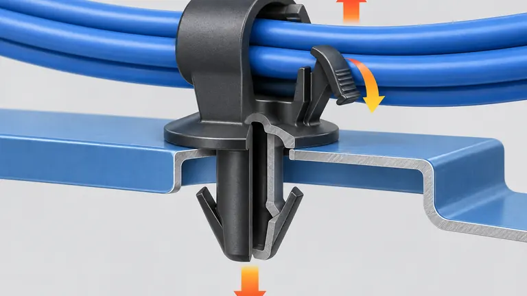
Conceptual illustration; not to scale.
Home › Blog › Automotive Wire Harness Clip DFM: Retention Force, Fit and Validation
Automotive sourcing and manufacturing decision guide
A harness clip can look simple in free-state CAD and still fail at the vehicle interface. A small change in hole size, panel thickness, coating, bundle diameter, approach angle, temperature, or load direction can raise assembly force, reduce retention, damage the harness, or prevent service removal. Nominal geometry alone hides those interactions.
Release clip DFM only after controlling the harness and vehicle-side interface ranges, installation and service sequence, separate insertion, retention, and removal definitions, tolerance combinations, material and long-term environment, moldability, and customer test methods. Evaluate the clip as an installed system with production-intent samples; do not infer universal force limits from another clip or a supplier catalog.
The core task is to connect every flexible molded feature to a real interface condition, force path, molding risk, and validation record before steel is committed.
In This Guide
- Freeze the Harness and Vehicle-Side Interface Inputs
- Separate Insertion, Retention and Removal Force
- Build the Worst-Case Fit and Force Tolerance Stack
- Automotive Wire Harness Clip DFM Checklist
- Select Material for the Condition After Time, Not Only First Fit
- Validation Input List Before Tool Release
- Release the Clip as an Interface, Not an Isolated Part
Freeze the Harness and Vehicle-Side Interface Inputs
Why this matters: Clip CAD often arrives without the controlled bundle, panel, hole, edge, stud, coating, access, or vehicle environment. A toolmaker can mold the shape but cannot judge whether it will install or retain correctly.
Freeze nominal and tolerance data for both sides of the interface, plus routing load, installation access, feedback, environment, service method, and customer ownership. Keep supplier catalog ranges as product clues, not acceptance criteria.
Commercial clip data demonstrates why interface ranges matter. One HellermannTyton automotive harness-clip page lists bundle diameter, hole diameter, panel thickness, polyamide grade and packaging as separate product parameters. TE Connectivity’s mounting-clip family uses different variants for different panel thicknesses. These are product examples, not acceptance values for a new design.
Obtain the nominal and tolerance for every mating input: wire/bundle/conduit diameter and ovality; tape or sleeve thickness; hole size/shape and burr direction; panel material/thickness/coating; edge radius; stud profile; nearby keep-outs; and installed harness preload.
Add assembly and vehicle context: installation direction and access, hand or tool operation, line takt, allowed audible/tactile feedback, routing bend, clip spacing, static/dynamic loads, temperature zones, fluids, vibration/shock and service removal.
Create an interface control sheet with drawings or measured data for the clip, harness, and vehicle feature in one installed coordinate system. On the harness side, include minimum, nominal, and maximum bundle or conduit diameter, ovality, tape or sleeve build, compressibility, abrasion limits, bend radius, routing preload, and clip spacing. On the vehicle side, include hole or slot shape, edge or stud profile, panel material and hardness, thickness, coating build, burr direction, local curvature, keep-outs, and stack position. Identify which organization controls each input and revision.
Add the production and service context. Record assembly direction, approach-angle range, hand or tool installation, takt and ergonomic limits, audible or tactile seating requirement, line visibility, mistake-proofing, service access, permitted removal tool, and reuse rule. Define static and dynamic load directions, vibration, shock, temperature-time profile, fluids, moisture, debris, and UV as applicable. Illustrative scenario: the clip fits the nominal bare panel, but the actual hole receives coating and the operator approaches off-axis behind a bracket. Those inputs belong in DFM before the lead-in and barb are finalized.
Harness side
- Bundle min/nominal/max and ovality
- Tape/sleeve/conduit construction
- Allowed compression/abrasion
- Routing preload and bend radius
Panel side
- Hole/slot/edge/stud geometry and tolerances
- Panel thickness and material hardness
- Coating, burr and surface condition
- Access, approach angle and keep-outs
Vehicle environment
- Temperature/time profile
- Vibration/shock and load directions
- Fluids, moisture, UV and debris
- Life cycles and service procedure
Separate Insertion, Retention and Removal Force
Why this matters: “Clip force” can refer to pushing into a panel, closing around a harness, resisting pull-out, preventing slip, or intentional service release. One value cannot describe these different functions.
Write a separate test definition for each force path with object, direction, support, approach, speed, displacement, conditioning, cycles, failure mode, and acceptance authority. Use force-displacement data when seating or release behavior matters.
Insertion force, retention force and removal force are different requirements: insertion controls assembly effort and seating; retention controls resistance to pull-out or displacement in named directions; removal controls an authorized service action and may be intentionally different from accidental pull-out.
Define the test object and force path. “Clip force” can mean push-in force of the clip into a panel, closing force around a harness, pull-out force from the panel, harness slip-out force, or service release force. Each can have different direction, speed, fixture, conditioning and pass/fail logic.
HellermannTyton’s edge-clip guidance explains that push-on and pull-off behavior depends on edge hardness/thickness, coating or contamination, temperature, harness torsion and vibration; it does not publish one universal mean value because the combinations are extensive.
Use a force-displacement trace when seating point, peak force or release mode matters. Record whether the clip fully seats, damages the panel/coating, whitens/cracks, partially backs out, releases as intended or transfers load into the harness.
Start with a free-body sketch of the installed clip and name the interfaces. For insertion, define whether force is applied to the clip head, harness, or tool; how the panel is supported; approach-angle tolerance; speed; stopping condition; seating confirmation; and allowable panel, coating, or clip damage. For retention, distinguish axial pull-out, lateral load, rotation, harness slip, and sustained preload. For service removal, define the authorized tool, access, actuation, direction, reuse decision, and post-removal inspection. Customer methods control the final fixture and values.
Do not reduce a complex trace to peak force alone. Record displacement at initial contact, barb deflection, seating event, peak, relaxation, release mode, and visual condition where relevant. A high insertion force may still fail to seat; a high pull value can result from panel damage; a clip can meet initial force and lose retention after thermal aging. Illustrative use scenario: assembly reports excessive push-in while the laboratory reports acceptable pull-out. Treat these as separate results and investigate lead-in, coating, panel stack, approach, material condition, and seating—not as contradictory measurements of one “clip force.”
Insertion / push-in
Question: Can the operator or tool seat the clip correctly?
Specify: direction, speed, support, approach angle, force limit and seating evidence.
Retention / pull-out
Question: Does the installed clip resist unintended load?
Specify: axial/lateral/rotational direction, preload, rate, duration, conditioning and failure mode.
Removal / service release
Question: Can authorized service remove/reopen it without unacceptable damage?
Specify: tool, access, direction, reuse rule and post-removal inspection.
Build the Worst-Case Fit and Force Tolerance Stack
Why this matters: Nominal samples can hide the two opposing risks: high insertion at tight or coated interfaces and low retention at loose or thin interfaces. Bundle extremes create a separate latch and abrasion stack.
Model functional extremes and credible combinations for panel, opening, coating, bundle, clip geometry, material condition, and installation angle. Let the design authority choose worst-case, statistical, or measured-population methods and validate more than nominal.
Evaluate at least the combinations that reduce engagement and those that maximize assembly load. A small hole with thick coating may increase insertion force; a large hole with thin panel may reduce retention. A large bundle can overstress a latch while a small bundle may rattle or slip.
Do not stack every independent tolerance arithmetically without understanding probability and functional relationship, but do not validate nominal-only samples either. The design authority should define worst-case, statistical or measured-population methods.
Illustrative example — method only: create four controlled interface conditions: minimum hole/thick panel, maximum hole/thin panel, minimum bundle and maximum bundle. Measure seating, damage, insertion and retention for each, then add temperature/aging conditions required by the customer. No numerical force or acceptance value is implied.
Build a stack worksheet around functional engagement. Identify dimensions and characteristics that control lead-in interference, barb deflection, engaged length, seating stop, anti-rotation, bundle compression, latch strain, and clearance. Include molded clip variation by cavity and process, panel and hole variation, coating, burr or edge radius, and assembly alignment. Distinguish independent dimensions from correlated manufacturing conditions so arithmetic worst-case is used deliberately rather than automatically. Where statistical treatment is proposed, document distributions, data source, confidence, and residual tail risk.
Use the illustrative four-condition matrix as a starting tool: tight opening/thick or coated panel for insertion risk; loose opening/thin panel for retention risk; minimum bundle for slip or rattle; maximum bundle for latch strain and assembly force. Add hot, cold, moisture-conditioned, aged, or fluid-exposed states required by the application. Record seating, force-displacement, damage, retention direction, and failure mode. If one physical combination cannot represent two independent extremes, build controlled fixtures or samples for each. Never insert generic force thresholds merely because another catalog clip uses a similar hole size.
High insertion risk
- Small/rough/coated opening
- Thick or hard panel
- Misaligned approach
- Cold/stiff clip condition
Low retention risk
- Large opening or thin panel
- Reduced barb engagement
- Softened/crept material
- Off-axis harness load
Harness-fit risk
- Bundle below grip range
- Bundle above latch capacity
- Tape compression/creep
- Abrasion at motion points
Automotive Wire Harness Clip DFM Checklist
Why this matters: Improving moldability can weaken the interface, while maximizing first-fit retention can create molding, assembly, fatigue, or service problems. Gate, weld, draft, ejection, and shrinkage decisions directly affect flexible features.
Review function and moldability together in the installed coordinate system. Connect each lead-in, barb, latch, cradle, stop, and anti-rotation feature to draft, parting, gate and weld lines, wall transitions, shrinkage, fiber orientation, ejection, inspection, and service access.
Review the part in its installed coordinate system and as a molded component. Record each decision and the interface revision used.
Use the checklist in a cross-functional DFM review. For function, confirm unambiguous lead-in and seating, sufficient engagement across tolerance, controlled harness compression, no sharp abrasion point, and correct anti-rotation without overconstraint. For molding, evaluate draw direction, undercuts and actions, draft, radii at flex roots, uniformity of wall and rib transitions, sink and warp, shutoffs, venting, gate location, weld-line position, cooling, ejection, and cavity marking. Flexible arms should be assessed in the molded and conditioned state, not only by linear CAD deflection.
Record tradeoffs and verification. Moving a gate can improve filling yet orient reinforcement or create a weld line near a barb. Increasing stiffness can improve nominal retention but raise insertion force and root strain. More draft helps release but can reduce engagement. A side action may improve functional geometry while increasing tool complexity and maintenance. For each decision, name the affected requirement, analysis or trial evidence, residual risk, and validation step. Ask the supplier for annotated DFM, proposed tool concept, gate and parting rationale, cavity and inspection strategy, and a list of required customer decisions before tool release.
| DFM checkpoint | Design review input |
|---|---|
| Function geometry | • Lead-in and seating stop are unambiguous • Barb/fir-tree/edge features engage at tolerance limits • Anti-rotation feature fits without overconstraint • Harness cradle/latch avoids pinch and abrasion |
| Moldability | • Parting line and draw direction support function • Draft and radii avoid scuff/crack • Wall/rib transitions manage sink/warp • Undercuts/actions and ejection are defined |
| Process influence | • Gate location avoids critical flex/appearance zones • Weld lines at retention features assessed • Fiber orientation/shrinkage considered • Cavity identification and inspection access provided |
| Assembly/service | • Operator access and ergonomic direction checked • Positive seating feedback defined • Removal tool/access and reuse rule defined • Incorrect orientation/misassembly risk addressed |
Select Material for the Condition After Time, Not Only First Fit
Why this matters: A resin that passes room-temperature first assembly may relax, creep, absorb moisture, embrittle, swell, or change stiffness after time, heat, fluids, vibration, and repeated service. Generic family names cannot predict this behavior.
Select the exact grade against time-dependent strain, temperature, moisture, chemicals, fatigue, impact, processing, shrinkage, color, and customer constraints. Use manufacturer data for screening and validate the molded clip after applicable conditioning.
Material selection should consider temperature/time, moisture, fluids, UV, impact, fatigue, stress relaxation, creep, color and customer material restrictions. A generic “nylon” designation is not enough to predict clip performance.
BASF’s Ultraform material brochure publishes creep-rupture behavior by grade and temperature and provides a snap-fit design tool. The specific material in a harness clip may be different, but the design lesson is transferable: long-term force/strain needs grade-specific data and conditioning, not an ambient first-assembly result.
Glass reinforcement can change stiffness, shrinkage and anisotropy; moisture conditioning can change polyamide behavior; hot/cold exposure can change insertion and retention. Use supplier data for the exact grade and validate the molded geometry in the customer environment.
Define the material load case before comparing datasheets: assembly strain, sustained deflection or preload, peak and minimum temperature, time at temperature, moisture state, oils or cleaners, UV, vibration, impact, required life cycles, and removal or reuse. Then obtain the exact manufacturer grade, reinforcement and additive package, conditioning basis, test method, specimen geometry, direction, and temperature behind the reported property. Short-term tensile modulus at one ambient condition is not a retention-after-aging prediction.
Consider process interaction. Glass reinforcement can increase stiffness while introducing anisotropic shrinkage, surface effects, and orientation sensitivity at a flexible arm. Polyamide moisture condition may materially change force behavior; another polymer family has different creep, chemical, or fatigue tradeoffs. Colorant, recycled content, regrind, weld lines, molding stress, and root radii can also affect performance. Use finite-element or snap-fit calculations as design aids with appropriate material models, then test production-intent parts across cavity and condition. No material is universally best for all harness clips.
Validation Input List Before Tool Release
Why this matters: Testing cannot be planned from a clip drawing and one force number. Missing interface variants, conditioning order, fixture definition, sample identity, or failure criteria makes results difficult to compare or reproduce.
Release a validation input matrix naming clip and interface variants, conditioning, force path, fixture, method, sequence, sample quantity basis, recorded data, failure modes, acceptance source, deviations, and approval authority.
Agree the inputs below before anyone writes a universal force target. The customer or design authority owns the final acceptance criteria.
Use the listed categories as columns, not a generic checklist. Identify clip revision, material/color, cavity and lot; panel, hole, edge, stud, coating, and harness combinations; control and conditioned groups; assembly orientation; insertion, retention, removal, vibration, thermal, fluid, and durability sequence; recovery time; fixture drawing and calibration; crosshead or actuation rate; preload and hold duration; displacement and force channels; visual or dimensional post-check; and sample disposition. Tie every numeric criterion to the customer drawing, specification, or authorized validation plan.
Plan sequencing because earlier work can influence later results. If installation damages coating or preloads the clip, preserve that state for the relevant retention test. If environmental exposure follows assembly, condition the installed system rather than loose parts unless the method says otherwise. Keep destructive populations separate and include controls. Illustrative scenario: hot-aged clips show lower pull-out force only on the thin-panel condition. The records should let engineering separate material relaxation, panel engagement, cavity variation, and test-fixture effects instead of reporting one averaged pass or fail.
| Validation input | Condition and acceptance basis |
|---|---|
| Samples and variants | • Clip material/color/cavity/lot • Panel/hole/edge/stud tolerance variants • Harness min/nominal/max constructions • Aged/conditioned and control groups |
| Test definitions | • Insertion/closure method and rate • Retention directions, preload and duration • Removal/service method and reuse rule • Force-displacement and failure-mode recording |
| Environment | • Temperature/humidity sequence • Vibration/shock orientation • Fluid/chemical/UV exposure • Assembly/aging order and recovery time |
| Acceptance and evidence | • Customer-defined numeric/functional criteria • No damage/rattle/back-out definitions • Sample identity and measurement uncertainty • Report, deviation and approval authority |
Release the Clip as an Interface, Not an Isolated Part
Why this matters: A clip can meet isolated drawing dimensions and still be incompatible with the released vehicle interface or validation state. Production teams need one synchronized definition and release boundary.
Release the clip drawing together with an interface control sheet, material and environment, installation and service method, DFM decisions, validation matrix, approved deviations, cavity/process baseline, and named customer or design authority.
Freeze the clip drawing together with an interface control sheet that names bundle, panel/hole/edge/stud ranges, installation direction, load directions, material and environment. Link the DFM record to the validation matrix so every critical feature has evidence.
Use the automotive DFM and mold-flow route to review the clip’s flex features, gate/weld-line risk and mold concept. The automotive injection molding materials page can frame grade-specific questions without substituting for an approved material specification. Start a controlled review through the project RFQ.
Scope boundary: This article is a planning aid, not an OEM approval rule. The released drawing, contract, customer-specific requirements and agreed validation plan control the actual project.
Create a release package index. It should connect clip CAD and drawing revision to the harness and vehicle-interface revisions; nominal and tolerance ranges; material manufacturer, grade, color and source rules; installation direction and seating evidence; force and environmental methods; DFM and tool decisions; inspection characteristics; production and cavity identification; test reports; deviations and expiry; and the approval record. If the interface changes after clip release, perform change impact rather than assuming the clip remains compatible.
At the final gate, ask six questions: Does every functional feature have a controlled mating input? Are insertion, retention, and service removal independently defined? Were critical tolerance and environmental combinations tested? Does the exact molded material and cavity population match the evidence? Are molding risks and inspection methods closed? Who is authorized to approve production and shipment? If any answer is provisional, state the limit and next evidence. This preserves the clip as one element of a controlled harness-and-vehicle system rather than an isolated molded commodity.
Conclusion
Before tool release, submit clip CAD and drawing, bundle range, panel or hole or edge data, coating, approach and service access, load directions, environmental profile, exact material constraints, and customer test methods. Use the interface matrix to close DFM and validation together; never adopt universal force values from an unrelated clip.
Related Decision Guides
- Automotive Injection Molding RFQ Checklist: Files, Volumes and Validation Requirements
- Can an Existing Automotive Plastic Part Be Reproduced Without a 3D CAD File?
- Planning a Pilot Production Run for Automotive Plastic Parts
Send the Clip and Its Real Interface Conditions
Provide clip CAD/drawing, bundle range, hole or edge geometry, panel thickness/coating, load directions, environmental profile and customer force/test method. DFM can then address fit and moldability together.
Request a Harness Clip DFM Review
If the inquiry popup does not open in your browser, use the full automotive project RFQ.