
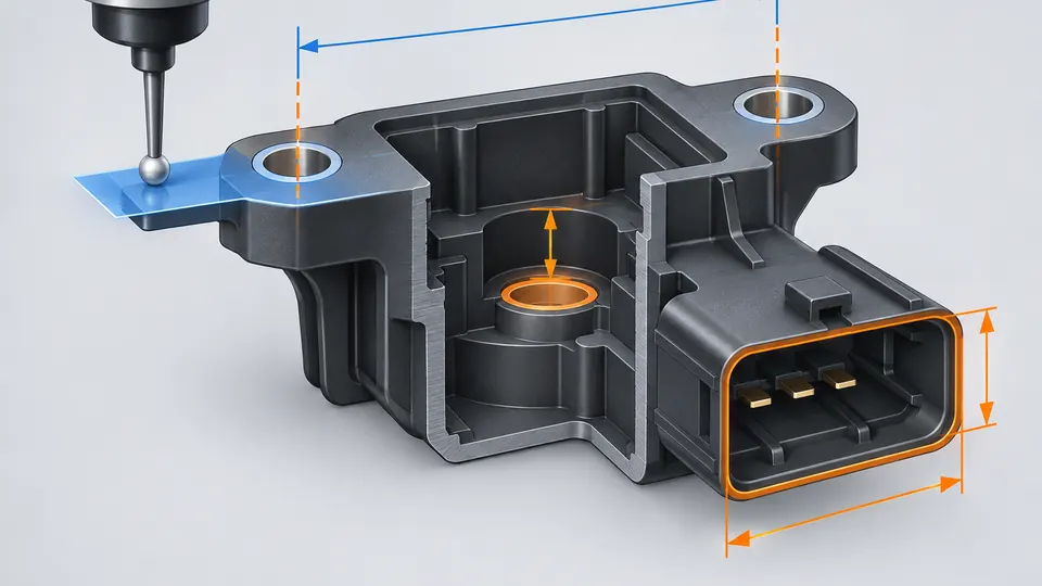
Conceptual illustration; not to scale.
An automotive sensor housing can look like a small, simple molding until the connector, fasteners, sensing element and vehicle bracket are checked together. If the drawing leaves the datum scheme or measurement state unclear, a supplier may build a mold that produces individually acceptable dimensions but a housing that does not locate or assemble consistently. The rework then appears after steel is cut.
Before tooling, define the functional interfaces, a repeatable datum reference frame, the dimensions that control assembly, the resin grade and moisture state, and the method and conditions used to measure each critical feature. The acceptance rule should identify the drawing revision, temperature and humidity, stabilization time, fixture or free-state condition, instrument, and evidence required. A supplier can then review manufacturability against a controlled requirement instead of guessing which dimensions matter.
The focus here is the dimensional definition of the housing. Sealing, ingress protection and sensor-performance validation may impose additional requirements, but they belong in their own specifications and test plans.
Start with the interfaces, not the nominal envelope
Why this matters: The outside envelope is easy to measure, but it is rarely the only reason a sensor housing fails. A connector may need a stable position, a bracket may control orientation, and an internal ledge may establish the sensor’s seating height. If those relationships are not identified, tightening every outside dimension creates cost without protecting the actual assembly.
The first question is: which features locate, retain, clear, protect or reference another component? Define those features as functional characteristics and connect each one to a mating part, a vehicle datum or an inspection fixture. The remaining surfaces can normally use a broader, process-appropriate requirement if they do not change assembly or performance.
Review the housing in an assembly context. Mark connector centerlines, bolt or clip axes, locating pins, mounting faces, sensor pockets, stop surfaces, cable exits and clearance envelopes. For each mark, record the mating feature, the direction of sensitivity and the consequence of error. A hole position may matter more than its diameter when a fastener must enter a bracket. An internal pocket may need a controlled profile or flatness even when its nominal depth is not visually important.
Use the same revision of the 3D model, 2D drawing, interface control drawing and mating-part definition. If the vehicle datum scheme is defined outside the part drawing, identify that document by number and revision. Do not infer a functional requirement from a CAD color, a screen measurement or a supplier’s usual practice. A feature is critical because the product definition or assembly function makes it critical, not because it looks small.
An early supplier review should return a marked-up feature list, proposed measurement method and questions about any missing mating condition. The output is not a promise that every feature will be held to a particular tolerance. It is a traceable decision about what the tool and process must protect.
Practical intake questions
- Which housing surfaces contact the vehicle bracket or sensor body?
- Which axes control connector insertion, terminal alignment or cable routing?
- Is the component measured assembled, on a checking fixture or in a free state?
- Are fasteners locating the housing, clamping it, or only preventing separation?
- Which dimensions are controlled by a separate mating-part or vehicle datum document?
Build a datum scheme that matches how the housing is used
Why this matters: A sensor housing can be measured from many convenient surfaces, but a convenient surface is not automatically a functional datum. A poor datum scheme can hide tilt, shift errors between features and make different suppliers report incompatible results. The drawing should make the inspection reference frame resemble the way the housing is located in the assembly.
Use a primary datum representing the principal mounting or seating plane, a secondary datum controlling orientation, and a tertiary datum removing the remaining translation or rotation needed for assembly. The exact letters and controls must follow the governing drawing standard and customer convention; this article does not prescribe a universal layout. Under ASME Y14.5, datum references and geometric controls communicate design intent for form, fit and function, while ISO GPS projects may use ISO rules. Select one interpretation system and state it.
The datum simulator also matters. A flat inspection plate may not represent a three-point vehicle mount. A pin can locate a hole, but a loose pin, floating clamp or oversized clearance can change the result. Define whether the part is constrained by pins, screws, clamps, nest surfaces or gravity. Identify which contacts are primary and which are only anti-drop or safety features. If the housing is flexible, specify clamp force or a low-distortion fixture concept rather than allowing an inspector to press the part into position.
Then connect each location control to the datum frame. Connector position, sensor pocket location and mounting-hole position should not be reported only as unrelated Cartesian distances unless that is the actual requirement. A profile control may better describe a complex seating surface. A position or orientation control may better describe an axis. The decision must be made by the design authority and confirmed with the customer where customer-specific rules apply.
Ask the supplier to show how the proposed mold parting line, slides, lifters, gates and ejection will influence the datum features. A datum on a cosmetic or flexible wall may be difficult to reproduce after ejection. A datum formed by a replaceable insert may be more maintainable than one spread across a moving shutoff. These are tooling decisions that should be visible before the mold design is frozen.
Also ask whether the inspection fixture uses the same locating sequence as the vehicle bracket. If not, record the reason and the expected relationship between the two setups. A fixture that constrains an otherwise free wall can create a result that is useful for assembly but not for mold correction. The report should therefore identify the controlled condition, the unconstrained condition and the decision each one supports. This small distinction prevents the supplier from correcting steel to compensate for a fixture that is pressing the housing into position.
Classify critical features and define their evidence
Why this matters: A drawing often contains more dimensions than a launch team can measure on every sample. The solution is not to label everything critical. Rank features by the failure they prevent, then assign a verification method that can distinguish the stated requirement from measurement noise.
Use at least four groups: assembly interfaces, internal component interfaces, datum and orientation controls, and general or cosmetic geometry. The first three groups may contain special characteristics, but not every item automatically requires capability studies or 100% inspection. The customer drawing, control plan and quality agreement determine mandatory treatment. For each feature, define the characteristic, nominal and tolerance or geometric control, datum reference, measurement method, sample timing, and reaction if the result is near or outside the limit.
The table below is a working definition tool. It is not a substitute for the approved drawing or customer-specific requirements. Use it during the DFM and inspection-plan review, and attach the evidence type that will actually be delivered.
| Housing feature | Input that must be defined | Preferred verification evidence | Typical risk if omitted |
|---|---|---|---|
| Mounting face and locating plane | Vehicle or bracket datum, contact condition, flatness/profile requirement | CMM or fixture measurement with datum setup documented | Housing rocks, tilts or shifts in the vehicle interface |
| Mounting holes, slots and clips | Mating hardware, axis, clearance, position control, insertion direction | CMM/vision report plus assembly or checking-gage result | Fastener will not enter or the part is forced into position |
| Connector opening and centerline | Connector model/revision, insertion envelope, orientation and clearance | CMM or dedicated functional gage with mating connector check | Connector misalignment, difficult insertion or cable strain |
| Internal sensor pocket | Sensor body, stop surfaces, clearances and seating datum | CMM/profile scan and fit check using an authorized master component | Sensor is tilted, loose or seated at the wrong height |
| Retention ledges and snap features | Assembly force, engagement position, release condition and mating material | Functional assembly test plus dimensional record | Incomplete engagement, breakage or inconsistent retention |
| Wall, ribs and boss locations | Fastener load path, insert clearance, sink/warpage sensitivity and draft | CMM/optical measurement of critical locations; visual review for molding defects | Local deformation changes fit even when the outer envelope passes |
| Connector or cable clearance | Cable bend/keep-out envelope and assembly sequence | Fixture or 3D scan comparison to the released envelope | Cable rub, blocked assembly or unplanned contact |
| Cosmetic or textured surface | Texture drawing, appearance limit sample and inspection lighting | Approved visual standard and controlled lighting record | Disagreement over texture, witness marks or gloss |
| Datum-to-feature relationship | Datum hierarchy and degrees of freedom to constrain | Report showing the datum setup and actual feature result | Two inspectors produce different conclusions from the same part |
Explain the table row by row with the supplier. A CMM report can show a hole position, but it does not prove that a connector can be inserted or that a clip survives assembly. Conversely, a functional gage can confirm the interface while hiding which underlying feature caused a failure. Critical evidence often needs both dimensional and functional checks, with the responsibilities stated in the inspection plan.
Use the evidence column to separate diagnosis from release. A CMM result can identify the location of a connector opening, while a mating-connector check can show whether the assembly actually works. The two records should share the same part revision, cavity and sample condition. For flexible housings, also state whether the scan was free-state or supported. If a characteristic is marked special, identify the customer or quality requirement that creates that status. If it is not special, retain a reason for the sampling and reaction plan selected. This avoids both under-inspection of a functional interface and over-inspection of a rib that has no demonstrated effect on the product. A report should also state whether the evidence is intended to release the part, diagnose the mold, or support a customer submission. Those purposes can use different sample counts and methods, so the status should travel with the result.
Control material state, environment and measurement timing
Why this matters: The same molded housing can produce different dimensional results when the resin, moisture state, temperature or elapsed time changes. This is especially important for hygroscopic materials, reinforced grades and thin or flexible housings. A report that omits the material designation and measurement conditions is difficult to compare with another report, even if the instrument is calibrated.
Record the exact resin manufacturer, grade, color or additive package, reinforcement, lot traceability and drawing-approved alternative status. Do not treat “PA66” or “nylon” as a complete material definition. The TDS, customer-approved list and processing requirements may distinguish grades with different shrinkage, moisture response and reinforcement orientation. If the drawing allows alternatives, define whether each alternative has its own dimensional baseline.
Define the state of the sample: immediately after molding, after a specified stabilization or conditioning protocol, after assembly, or after a defined storage and packaging history. For a moisture-sensitive resin, the supplier’s grade-specific processing and conditioning guidance is more relevant than a generic time copied from another project. BASF’s Ultramid guidance, for example, explains that moisture absorption affects dimensions and that the time to reach a normal moisture state depends on wall thickness and conditioning conditions. It does not create a universal acceptance time for every polyamide housing.
The measurement environment should include air temperature, relative humidity, sample temperature, stabilization time and whether the part was removed from packaging just before measurement. If the part is flexible, record the fixture, support points, clamp force or free-state orientation. Use a thermal soak or stabilization method agreed by both parties when the housing is measured against tight location requirements. The goal is repeatability, not an impressive-looking report generated under an undocumented condition.
Measurement uncertainty also belongs in the conversation. ISO 14253-1 addresses conformity decisions when a result is close to a specification limit by taking measurement uncertainty into account. The buyer and supplier should agree how close-to-limit results are handled, which decision rule applies, and when a result is reported as indeterminate or requires a second method. A calibrated instrument alone does not resolve an unstable fixture or an ambiguous datum.
For a launch study, measure a small but representative set after the condition is established and retain the condition record with the raw results. Include the direction of any material or fiber orientation that could affect the feature. If the measured value is close to a limit, record the decision rule instead of silently rounding the result. A buyer can then distinguish a real mold shift from a change in temperature, moisture, support or reporting convention.
Freeze a pre-tooling definition and acceptance record
Why this matters: The last step before steel is to convert the discussion into a controlled record. Without a baseline, later changes to the mating sensor, connector, resin or fixture can be mistaken for mold instability. The record should be concise enough to use, but detailed enough to reproduce the decision.
Create a sensor-housing tolerance pack containing the latest 2D drawing and 3D model, interface and datum documents, material specification, critical-characteristic list, inspection method, fixture concept, measurement environment, sample state, required reports and approval owners. Mark every unresolved assumption with an owner and a gate date. A blank field is not an acceptable release condition; the release should say whether the item is not applicable, customer-owned, or still open.
Ask the toolmaker to return a DFM response that identifies where the proposed parting line, gate, ejector, insert, weld line or fiber orientation may influence each critical feature. The response should distinguish a geometry change request from a process-control suggestion. If the supplier proposes a broader tolerance because of molding variation, the design authority must decide whether the functional requirement can change. A supplier cannot silently reinterpret the drawing through a quotation.
During T1, compare parts using the same datum scheme and sample-state definition. If the first report uses a free-state scan and the second uses a clamped fixture, the numerical difference may reflect the method rather than a mold correction. Keep the original result, revised result, fixture state and reason for change in the record. This supports a rational correction sequence and makes later repeat-order comparisons more meaningful.
Illustrative example: a housing has two mounting holes, a connector opening and an internal sensor stop. The first draft controls the outside length tightly but gives no datum reference for the connector. The review changes the priority: the mounting plane and hole axes become the assembly frame, connector position is checked against the mating connector, and the internal stop is measured in the sensor seating direction. The outside length remains controlled, but it no longer consumes inspection effort that does not protect the assembly.
The release owner should sign off the feature map, while the measurement owner signs off the method and the toolmaker signs off the correction feasibility. Keep an assumptions register for items such as a mating connector revision, clamp force or sample conditioning. When an assumption changes, assess the affected characteristics before updating the mold. This turns the pack into a living configuration record rather than a static collection of screenshots and reports.
Conclusion
Before approving the mold, issue a controlled tolerance pack: functional interfaces, datum setup, critical-feature table, material state, environment, fixture condition, measurement method and close-to-limit decision rule. Send the released drawing and 3D data through the automotive DFM and moldflow review service or request an automotive DFM and quote review with the mating interfaces identified.
References
- ASME, Dimensioning and Tolerancing / Y14.5 — scope of GD&T language, datum references and design intent.
- ISO, ISO 14253-1:2017 — conformity decisions and measurement uncertainty near specification limits.
- NIST, Measurement Uncertainty — measurement as a process and the meaning of uncertainty.
- BASF, Ultramid brochure — grade-dependent moisture conditioning and dimensional state.