
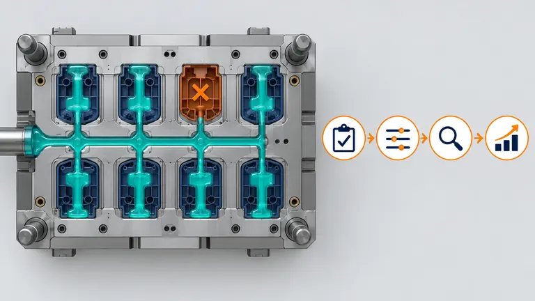
Blocking a damaged cavity may keep a delivery line moving, but it changes the feed system, shot size, residence time, balance, capacity, traceability, and approved process. Continuing without evaluation can protect today’s shipment while creating a new quality or approval failure.
Production may continue only after the tool can be blocked safely, a new common process produces conforming parts in every active cavity, capacity remains sufficient, and the customer authorizes any required deviation or change. Treat the blocked configuration as a controlled temporary or permanent state—not an informal press-floor adjustment.
Determine why the cavity is being blocked and whether the hardware supports it
The first decision is not how to set the press. It is whether the failure mechanism and mold architecture allow the affected cavity to be isolated without creating additional damage or uncontrolled melt behavior.
Identify the defect and its boundary: cavity steel damage, broken core, gate or hot-runner problem, cooling leak, ejection failure, flash, dimensional drift, appearance issue, or downstream detection problem. Quarantine parts from the suspect period by cavity and lot. A blocked cavity does not correct parts already produced or remove the root cause.
Review the feed system. An individually actuated valve gate may support a designed cavity shutoff, but the manufacturer’s permitted procedure, controller logic, residual melt, thermal balance, and maintenance requirements still apply. A cold-runner cavity may require an engineered runner/gate plug or insert; an improvised obstruction can break loose, trap material, create dead spots, or damage the runner. Confirm whether the block is reversible and how its identity is controlled.
Inspect interactions with cooling, ejection, slides, lifters, sensors, and mold protection. A cavity with a water leak or broken moving action may remain unsafe even if no resin enters it. The mold designer or responsible tooling authority should approve a repair or shutdown method and define inspection before cycling.
Document the normal and blocked configurations: active cavity list, hot-runner zones and valve state, inserts or plugs installed, water circuits, controller recipe, process revision, and physical identification. Apply lockout and safety procedures during tool work. Do not rely on a handwritten note at the press.
RJG notes that cavity fill-time data can help detect blockage and balance changes in multi-cavity molds (RJG cavity fill-time overview). Detection does not authorize continued production; it supplies evidence for containment and engineering review.
Re-establish the molding process for the changed cavitation
Removing one flow path changes the relationship between machine shot, runner volume, active part volume, filling resistance, packing, and cycle. Reusing the old recipe without study can overfill or overpack remaining cavities.
Calculate the new theoretical shot requirement from active part volume plus the actual feed-system volume that still fills. Verify screw position, cushion, injection-unit capacity, and residence time for the reduced throughput. A much smaller shot can place the process outside the machine or resin supplier’s recommended operating condition. Check purge and startup behavior, especially for thermally sensitive materials and hot runners.
Run controlled fill-only studies for every active cavity. Compare fill sequence and part weight with the approved baseline. Then establish transfer, pack/hold, cooling, and recovery settings using material and machine variables—not simply percentage reductions from the old recipe. Monitor peak pressure, cushion, recovery, melt and mold temperature, and cavity pressure when available.
Autodesk’s guidance explains that unbalanced flow can cause flash, short shots, density differences, warpage, air traps, and weld-line changes, and that multi-cavity systems should fill cavities at similar time and pressure (Autodesk unbalanced flow). Blocking one cavity can disturb a previously balanced network, particularly in cold runners or systems without independent control.
Check thermal effects. An inactive hot-runner drop may need a defined standby or shutdown condition; leaving degraded resin in a dead region can create contamination or startup risk. Cooling balance can also change if a circuit is isolated. Follow equipment and resin supplier instructions.
Record a new process setup and permitted window for the exact mold/material/machine/cavitation combination. If a robust window cannot be demonstrated without compromising active cavities, the correct decision is repair, alternative tool, or approved supply recovery—not continued blocked-cavity production.
Validate every active cavity and obtain the required authorization
A blocked configuration is a manufacturing change. The team must show that active cavities still meet product requirements and determine whether customer notification, deviation, or resubmission is required.
Build an affected-risk matrix covering fill and pack, dimensions, warpage, appearance, weld lines, material residence, cooling, cycle, traceability, inspection, packaging, and capacity. Compare the new configuration to the approved baseline. Use production-intent resin and the intended machine, automation, gauges, and packaging.
| Evidence | Required comparison | Release decision |
|---|---|---|
| Fill-only and process traces | Normal versus blocked cavitation | Common active-cavity window exists |
| Cavity-identified dimensions | All affected drawing/assembly features | Each active cavity conforms |
| Appearance and gate results | Customer master/boundary | No new visible effect |
| Functional/assembly test | Production-intent mating conditions | Function remains acceptable |
| Material history | Residence, drying, color, regrind | Material rules remain satisfied |
| Traceability and controls | Cavity map, label, reaction plan | Mixed or inactive cavities are prevented |
Illustrative example—hypothetical, not an AutoMoldingPro project. One cavity in an eight-cavity clip mold damages a core pin. The tool has no validated individual shutoff. Engineering installs a designed runner insert, records the configuration, and runs a seven-cavity process study. Weight and fill order shift, requiring a new transfer point. Parts are measured and assembly-tested by cavity, and effective capacity is recalculated before a time-limited customer deviation is requested. This example does not imply that every runner can be plugged safely.
IATF’s published sanctioned interpretation states that customer authorization is required before further processing when product or manufacturing process differs from the currently approved condition (IATF 16949 sanctioned interpretations). Apply the current applicable standard, customer-specific requirements, and internal change process; do not rely on this article as the authorization itself.
The approval record should state active cavities, duration or quantity, affected part numbers, validation evidence, inspection/containment, labeling, repair plan, and expiration.
Recalculate effective capacity, cost, and supply risk
Blocking a cavity reduces output per cycle and may alter cycle time, scrap, labor, maintenance, and material loss. A tool that remains technically capable may still fail the customer’s delivery requirement.
Calculate good pieces per hour from active cavities, demonstrated stable cycle, actual uptime, and verified yield. Do not use nominal cavitation alone. Include planned maintenance, changeover, startup loss, inspection or containment, and any slower cycle needed for the blocked process. Compare available hours with firm releases and approved forecast assumptions.
For example, define: effective good output = active cavities × cycles per scheduled hour × demonstrated uptime × first-pass yield. Keep units visible and use actual agreed inputs. If one of eight cavities is blocked, output does not necessarily fall by exactly one eighth because cycle, uptime, scrap, or inspection may also change. Do not promise capacity until the revised process is demonstrated.
Review unit cost transparently. Fixed labor and machine time are spread across fewer pieces; runner waste per accepted part can increase in a cold-runner tool; added sorting or measurement adds cost. Separate temporary containment cost from a permanent price change. A supplier should not use an emergency state to hide unrelated commercial adjustments, and a buyer should not assume the original price remains viable indefinitely.
Build a dated recovery plan: usable inventory, confirmed demand, revised output, overtime or alternate capacity, repair parts, tool downtime, revalidation, and return to normal cavitation. If the blocked configuration becomes long term, evaluate whether the runner, hot-runner controls, process, maintenance plan, and customer approval should be redesigned formally.
Link capacity evidence to the run-at-rate validation process. A brief sample run proves product learning; a production-length run demonstrates whether seven cavities can meet rate, quality, and operational constraints.
Control the temporary state and restore the approved configuration
Temporary configurations tend to become permanent when ownership and expiration are vague. Manage the blocked cavity with configuration control, visual identification, scheduled review, and a defined restoration gate.
Issue an approved change or deviation record with reason, active cavities, tool configuration, process revision, inspection, containment, effective time/lot, expiration, authorized quantity, customer approval, and responsible owner. Update the setup sheet, cavity map, control plan or temporary instruction, maintenance record, label rules, and production scheduling. Train operators and inspectors on the changed cavity pattern.
Prevent accidental reactivation. The physical block, valve setting, heater state, and controller recipe should be controlled. On each setup, verify the configuration against the record. Monitor active-cavity weight, dimensions, appearance, and process indicators at the defined frequency. Define reaction to drift or a second cavity problem.
Repair the root cause under a separate plan. Before restoring full cavitation, inspect the repaired component and related systems, remove the block, verify runner/gate and hot-runner state, reconnect cooling or sensors, and re-establish the approved process. Run cavity-balance and product checks against the original baseline. Customer requirements determine reapproval.
Preserve data from both states. Future maintenance teams need to know which parts were made under the blocked configuration and which tool components were changed. If the tool transfers, include this history and confirm no temporary hardware remains undocumented.
For a production decision, provide the failure evidence, mold design and feed system, normal process, cavity-specific quality data, demand, inventory, customer change rules, and repair timing. Ask the molder for a safe block method, new process study, validation matrix, capacity calculation, cost impact, controls, and restoration plan. Continue only when those records support the same product and delivery obligations.
Conclusion
Do not block a cavity and reuse the old process by default. First make the tool safe, establish a new cavitation-specific process, validate every active cavity, obtain required customer authorization, and prove capacity. Time-limit the condition and define how the approved configuration will be restored.