
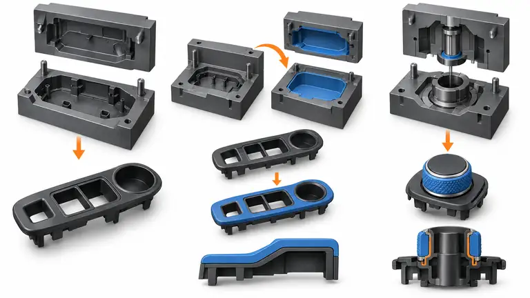
A soft grip, seal or vibration layer can improve an automotive component, but it can also add a mold, a material interface, handling and another validation path. The soft-touch overmolding guide explains how to design that interface — substrate, bonding, and tooling — once the second material is justified. If the function is vague, the team may pay for permanent process complexity to solve a preference that a single material or separate component could meet.
Added tooling is justified only when the second material provides a measurable requirement and the selected route has the best supportable lifecycle case. Compare single-shot molding, separate assembly, transfer overmolding and two-shot molding using the same part revision, material pair, volume, yield, cycle, labor, quality and validation scope. Where the consolidation is one rigid molding rather than a soft/hard material combination, the joint-removal decision is worked through here: Part Consolidation in Automotive Plastic Assemblies: Which Joints Should Stay Separate?.
The review should move from function to interface evidence, then from production route to cost and release gates.
Use this guide when you need to decide whether the second material is worth its tooling. This guide compares the routes — single-shot, separate assembly, transfer overmolding, and two-shot — and works out at which volume each one wins. It does not teach substrate and TPE bonding: for how a material pair is selected, how the interface retains the soft layer, and how the tool is designed around it, see Soft-Touch Automotive Overmolding: Substrate, Bonding, and Tool Design. It does not build the per-good-part unit cost either: for how material, conversion, downstream work, and packaging reconcile into one piece price, see What Drives Automotive Molded Part Pricing? Material, Cycle Time, and Inspection. And it does not decide whether one tooling investment pays back: for the break-even volume of a single investment, see Break-Even Volume for Automotive Injection Tooling: A Worked Decision Framework. Use this guide to choose the route, 473 to qualify the interface, 368 to price the part, and 559 to test the investment.
Start with the function of the second material
the seal, grip, damping, impact, appearance or insulation requirement that the soft or second material must deliver can change cost, function and release evidence if it is decided after the quotation or tool concept is fixed.
Define mapping each function to a measurable surface, load, environment and acceptance method before commitment. Use project-specific inputs and an acceptance record; do not assume that a familiar process is automatically suitable for this part.
The review should begin with the physical function rather than a preferred manufacturing answer. The technical focus is the seal, grip, damping, impact, appearance or insulation requirement that the soft or second material must deliver. Put that focus into the drawing, interface definition, quotation or validation plan that governs the work. Use the exact grade, geometry and condition under review, and identify connected characteristics that may move with the decision.
Use this sequence: mapping each function to a measurable surface, load, environment and acceptance method. Assign unresolved inputs to named owners, freeze the working revision and state the next commitment that would be costly to reverse. Trials should use representative material, tooling, equipment and handling; a prototype or illustrative comparison must remain clearly identified when it is not production evidence.
The minimum inputs are mating geometry, contact pressure, user touch zone, temperature and fluids, life cycles and appearance boundary. Check units, conditioning, sample identity and requirement source. Request controlled customer documents instead of guessing proprietary rules. A separate gasket may simplify molding but add assembly; an integrated layer removes a component while making the interface permanent. Preserve the rejected alternative and its reason because volume, environment, appearance, assembly or equipment changes can reverse the choice.
The main failure path is adding a second material without a testable requirement, then treating tactile preference as proof of durability. Isolate variables and watch coupled effects on dimensions, appearance, strength, cycle or inspection. Closure requires a signed function list and product-level test plan show why one material cannot meet the requirement. Connect original evidence to part and drawing revision, cavity or fixture, material lot and process state; then record both an acceptance condition and a reaction that tells production when to stop or reopen the review.
Compare all feasible manufacturing routes
single-shot geometry, a separately assembled soft part, manual transfer overmolding and automated two-shot molding can change cost, function and release evidence if it is decided after the quotation or tool concept is fixed.
Define quoting every route on the same delivered-part definition and volume scenarios before commitment. Use project-specific inputs and an acceptance record; do not assume that a familiar process is automatically suitable for this part.
Treat this as a controlled interface between design intent and production evidence. The technical focus is single-shot geometry, a separately assembled soft part, manual transfer overmolding and automated two-shot molding. Put that focus into the drawing, interface definition, quotation or validation plan that governs the work. Use the exact grade, geometry and condition under review, and identify connected characteristics that may move with the decision.
Use this sequence: quoting every route on the same delivered-part definition and volume scenarios. Assign unresolved inputs to named owners, freeze the working revision and state the next commitment that would be costly to reverse. Trials should use representative material, tooling, equipment and handling; a prototype or illustrative comparison must remain clearly identified when it is not production evidence.
The minimum inputs are part and substrate CAD, material pair, annual and order volume, available machines, handling method, secondary assembly and packaging. Check units, conditioning, sample identity and requirement source. Request controlled customer documents instead of guessing proprietary rules. Low volume may favor simple tools and handling; higher repeat volume may support automation, but no universal threshold replaces the calculation. Preserve the rejected alternative and its reason because volume, environment, appearance, assembly or equipment changes can reverse the choice.
The main failure path is comparing a bare single-shot molding price with a finished overmolded assembly or omitting transfer rejects. Isolate variables and watch coupled effects on dimensions, appearance, strength, cycle or inspection. Closure requires scope-aligned quotations identify tooling, fixtures, cycle, labor, yield, maintenance and included validation. Connect original evidence to part and drawing revision, cavity or fixture, material lot and process state; then record both an acceptance condition and a reaction that tells production when to stop or reopen the review.
Qualify material compatibility and retention
chemical adhesion, mechanical interlocks, shut-offs, flow length and differential shrinkage at the rigid-soft interface can change cost, function and release evidence if it is decided after the quotation or tool concept is fixed.
Define selecting exact grades with supplier guidance, designing retention, and molding representative plaques or parts before release before commitment. Use project-specific inputs and an acceptance record; do not assume that a familiar process is automatically suitable for this part.
The useful question is not whether the option can work once, but whether its boundary conditions are visible. The technical focus is chemical adhesion, mechanical interlocks, shut-offs, flow length and differential shrinkage at the rigid-soft interface. Put that focus into the drawing, interface definition, quotation or validation plan that governs the work. Use the exact grade, geometry and condition under review, and identify connected characteristics that may move with the decision.
Use this sequence: selecting exact grades with supplier guidance, designing retention, and molding representative plaques or parts before release. Assign unresolved inputs to named owners, freeze the working revision and state the next commitment that would be costly to reverse. Trials should use representative material, tooling, equipment and handling; a prototype or illustrative comparison must remain clearly identified when it is not production evidence.
The minimum inputs are rigid substrate grade and color, elastomer grade and hardness, thickness, surface state, storage, melt history and service media. Check units, conditioning, sample identity and requirement source. Request controlled customer documents instead of guessing proprietary rules. Chemical bonding and mechanical retention are the two ways the soft layer stays on the substrate, and choosing between them is a material-pair decision, not a route decision — the pair selection, the retention design, and the tooling consequences are worked out in Soft-Touch Automotive Overmolding: Substrate, Bonding, and Tool Design; this guide takes the qualified pair as its input and asks only whether the route that carries it is justified. Preserve the rejected alternative and its reason because volume, environment, appearance, assembly or equipment changes can reverse the choice.
The main failure path is assuming any TPE bonds to any rigid plastic or crediting an attractive first sample before conditioning. Isolate variables and watch coupled effects on dimensions, appearance, strength, cycle or inspection. Closure requires aged peel, pull or functional tests and sections confirm the exact pair and interface under specified conditions. Connect original evidence to part and drawing revision, cavity or fixture, material lot and process state; then record both an acceptance condition and a reaction that tells production when to stop or reopen the review.
Build the tooling and cell concept
the number of molds, transfer orientation, rotary platen or robot, shut-off wear, cooling and error proofing can change cost, function and release evidence if it is decided after the quotation or tool concept is fixed.
Define reviewing tool sections and the complete production cell before comparing cycle or capital before commitment. Use project-specific inputs and an acceptance record; do not assume that a familiar process is automatically suitable for this part.
A supplier recommendation becomes actionable only when its assumptions can be checked against the released product. The technical focus is the number of molds, transfer orientation, rotary platen or robot, shut-off wear, cooling and error proofing. Put that focus into the drawing, interface definition, quotation or validation plan that governs the work. Use the exact grade, geometry and condition under review, and identify connected characteristics that may move with the decision.
Use this sequence: reviewing tool sections and the complete production cell before comparing cycle or capital. Assign unresolved inputs to named owners, freeze the working revision and state the next commitment that would be costly to reverse. Trials should use representative material, tooling, equipment and handling; a prototype or illustrative comparison must remain clearly identified when it is not production evidence.
The minimum inputs are mold layout, press injection units, platen and tie-bar limits, robot reach, substrate nests, presence sensing and cooling demand. Check units, conditioning, sample identity and requirement source. Request controlled customer documents instead of guessing proprietary rules. Two-shot automation can remove handling but raises machine and tool specialization; transfer tooling is flexible but adds work content. Preserve the rejected alternative and its reason because volume, environment, appearance, assembly or equipment changes can reverse the choice.
The main failure path is selecting a route the destination plant cannot run or leaving soft-material flash at an exposed boundary. Isolate variables and watch coupled effects on dimensions, appearance, strength, cycle or inspection. Closure requires approved tool and cell layouts demonstrate loading, location, sensing, ejection and maintainable shut-offs. Connect original evidence to part and drawing revision, cavity or fixture, material lot and process state; then record both an acceptance condition and a reaction that tells production when to stop or reopen the review.
Calculate lifecycle cost and capacity
fixed investment, saleable output, labor, scrap, material loss, maintenance and change exposure across demand cases can change cost, function and release evidence if it is decided after the quotation or tool concept is fixed.
Define calculating totals for low, expected and high volume with the same accepted-part and delivery basis before commitment. Use project-specific inputs and an acceptance record; do not assume that a familiar process is automatically suitable for this part.
Separate the mechanism being controlled from the document used to report it. The technical focus is fixed investment, saleable output, labor, scrap, material loss, maintenance and change exposure across demand cases. Put that focus into the drawing, interface definition, quotation or validation plan that governs the work. Use the exact grade, geometry and condition under review, and identify connected characteristics that may move with the decision.
Use this sequence: calculating totals for low, expected and high volume with the same accepted-part and delivery basis. Assign unresolved inputs to named owners, freeze the working revision and state the next commitment that would be costly to reverse. Trials should use representative material, tooling, equipment and handling; a prototype or illustrative comparison must remain clearly identified when it is not production evidence.
The minimum inputs are tool and fixture price, material usage, cycle, cavities, yield, staffing, setup, preventive maintenance, validation and forecast timing. Check units, conditioning, sample identity and requirement source. Request controlled customer documents instead of guessing proprietary rules. The lowest modeled unit cost may require more cash and less flexibility; a simpler route can be rational when demand or design remains uncertain. How that unit cost is built — material, conversion, downstream work, and packaging reconciled into one per-good-part total — is in What Drives Automotive Molded Part Pricing? Material, Cycle Time, and Inspection; this guide compares the routes’ totals, it does not build the piece price. Preserve the rejected alternative and its reason because volume, environment, appearance, assembly or equipment changes can reverse the choice.
The main failure path is using theoretical shots instead of accepted output or hiding second-shot losses inside a general overhead rate. Isolate variables and watch coupled effects on dimensions, appearance, strength, cycle or inspection. Closure requires a transparent model identifies the crossover drivers and confirms peak-week capacity as well as lifetime economics. The crossover in this guide compares routes against each other; whether one tooling investment on its own pays back at the expected volume is a separate break-even decision, worked out in Break-Even Volume for Automotive Injection Tooling: A Worked Decision Framework. Connect original evidence to part and drawing revision, cavity or fixture, material lot and process state; then record both an acceptance condition and a reaction that tells production when to stop or reopen the review.
Release with interface and process evidence
the evidence needed to approve appearance, adhesion, dimensions, sealing and repeatability without confusing a sample with production capability can change cost, function and release evidence if it is decided after the quotation or tool concept is fixed.
Define running representative trials, tracing both material lots, and defining ongoing checks and change triggers before commitment. Use project-specific inputs and an acceptance record; do not assume that a familiar process is automatically suitable for this part.
Close this point at the level of the specific feature, material state, process step or inspection result. The technical focus is the evidence needed to approve appearance, adhesion, dimensions, sealing and repeatability without confusing a sample with production capability. Put that focus into the drawing, interface definition, quotation or validation plan that governs the work. Use the exact grade, geometry and condition under review, and identify connected characteristics that may move with the decision.
Use this sequence: running representative trials, tracing both material lots, and defining ongoing checks and change triggers. Assign unresolved inputs to named owners, freeze the working revision and state the next commitment that would be costly to reverse. Trials should use representative material, tooling, equipment and handling; a prototype or illustrative comparison must remain clearly identified when it is not production evidence.
The minimum inputs are customer approval plan, samples across cavities and time, conditioning, failure criteria, process window and reaction plan. Check units, conditioning, sample identity and requirement source. Request controlled customer documents instead of guessing proprietary rules. Broader testing costs time and samples; mechanism-based testing keeps the scope proportional while protecting the claimed function. Preserve the rejected alternative and its reason because volume, environment, appearance, assembly or equipment changes can reverse the choice.
The main failure path is approving on room-temperature appearance alone or changing a substrate grade without repeating interface review. Isolate variables and watch coupled effects on dimensions, appearance, strength, cycle or inspection. Closure requires traceable trial data, approved limits and production control records support the complete overmolded part. Connect original evidence to part and drawing revision, cavity or fixture, material lot and process state; then record both an acceptance condition and a reaction that tells production when to stop or reopen the review.
Overmolding route decision worksheet
Use this worksheet—the overmolding route decision worksheet—during the supplier review. It is a decision aid for decide whether a second material and added tooling are justified by a defined product function and lifecycle business case., not a substitute for the drawing, customer specification or validation record.
| Review line | Required input or evidence | Release question |
|---|---|---|
| Start with the function of the second material | mating geometry, contact pressure, user touch zone, temperature and fluids, life cycles and appearance boundary | Is a signed function list and product-level test plan show why one material cannot meet the requirement available and traceable? |
| Compare all feasible manufacturing routes | part and substrate CAD, material pair, annual and order volume, available machines, handling method, secondary assembly and packaging | Is scope-aligned quotations identify tooling, fixtures, cycle, labor, yield, maintenance and included validation available and traceable? |
| Qualify material compatibility and retention | rigid substrate grade and color, elastomer grade and hardness, thickness, surface state, storage, melt history and service media | Is aged peel, pull or functional tests and sections confirm the exact pair and interface under specified conditions available and traceable? |
| Build the tooling and cell concept | mold layout, press injection units, platen and tie-bar limits, robot reach, substrate nests, presence sensing and cooling demand | Is approved tool and cell layouts demonstrate loading, location, sensing, ejection and maintainable shut-offs available and traceable? |
| Calculate lifecycle cost and capacity | tool and fixture price, material usage, cycle, cavities, yield, staffing, setup, preventive maintenance, validation and forecast timing | Is a transparent model identifies the crossover drivers and confirms peak-week capacity as well as lifetime economics available and traceable? |
| Release with interface and process evidence | customer approval plan, samples across cavities and time, conditioning, failure criteria, process window and reaction plan | Is traceable trial data, approved limits and production control records support the complete overmolded part available and traceable? |
For the decision to decide whether a second material and added tooling are justified by a defined product function and lifecycle business case., read the rows together. A technically acceptable feature can still be commercially incomplete, and a complete quotation can still rely on an unverified process assumption. Mark each row accepted, accepted with a bounded action, or open. A bounded action needs an owner, due date, quantity or activity limit and the evidence required for final closure.
Worked decision scenario
Consider this decision pattern. An interior control bezel needs a soft perimeter because the initial requirement says “premium feel.” The team first separates tactile preference from a possible rattle-control function. A textured single-shot grade, a separate elastomer ring, manual transfer overmolding and a two-shot tool are quoted on the same annual demand. Representative material-pair trials confirm adhesion only for selected grades. The separate ring wins while volume and styling remain uncertain; the drawing preserves a future two-shot route if demand and functional testing justify it.
For overmolding vs single shot molding, the decision remains conditional on the stated geometry, material, load, environment, quantity and acceptance method. Changing one of those inputs reopens the affected review line.
Worked crossover example — at which volume each route wins (illustrative)
Illustrative example — hypothetical teaching numbers, not an AutoMoldingPro quotation and not a real supplier price. Every input below is assumed for the purpose of showing the arithmetic; substitute the actual tooling prices, unit costs, and volumes from scope-aligned quotations before using this method on a real decision. No figure in this example is taken from any other supplier’s page, and no threshold in it is a general rule.
Assumed inputs (all stated, none hidden): one accepted part, same delivered-part definition and same annual demand for every route. Route A — single-shot substrate plus a separate elastomer ring, assembled: one-time tooling USD 10,000; recurring cost USD 1.20 per accepted part (molding, ring, and assembly labour). Route B — transfer overmolding, two tools: one-time tooling USD 22,000; recurring cost USD 0.95 per accepted part. Route C — two-shot molding, one rotary tool: one-time tooling USD 45,000; recurring cost USD 0.70 per accepted part. Validation, maintenance, and change exposure are held equal across the three routes and excluded from this illustration — the buyer must add them from the lifecycle-cost section before deciding. Tooling is a one-time fixed investment with no residual value and no discounting in this example.
The crossover volume between two routes is (tooling of the dearer route − tooling of the cheaper route) ÷ (recurring cost of the cheaper route − recurring cost of the dearer route). Route B overtakes Route A at (22,000 − 10,000) ÷ (1.20 − 0.95) = 12,000 ÷ 0.25 = 48,000 parts. Route C overtakes Route B at (45,000 − 22,000) ÷ (0.95 − 0.70) = 23,000 ÷ 0.25 = 92,000 parts. Route C overtakes Route A at (45,000 − 10,000) ÷ (1.20 − 0.70) = 35,000 ÷ 0.50 = 70,000 parts — but Route B still wins between 48,000 and 92,000 parts, so the direct A-to-C crossover is not the decision point.
Total cost (tooling + recurring cost × volume) at three volumes:
| Annual volume | Route A: single-shot + ring | Route B: transfer overmolding | Route C: two-shot | Cheapest route |
|---|---|---|---|---|
| 20,000 parts | USD 34,000 | USD 41,000 | USD 59,000 | A |
| 60,000 parts | USD 82,000 | USD 79,000 | USD 87,000 | B |
| 120,000 parts | USD 154,000 | USD 136,000 | USD 129,000 | C |
At 20,000 parts the separate ring wins because the tooling premium of either overmolding route cannot be recovered; at 60,000 parts transfer overmolding wins by USD 3,000 over the ring; at 120,000 parts two-shot wins by USD 7,000 over transfer. The lowest unit cost at any volume is not the decision — the total at the buyer’s actual volume is. If any assumed input changes, every crossover moves with it: that is the point of the model, and it is why the article warns against a universal volume threshold. Ask each supplier for the same three numbers — tooling, recurring cost per accepted part, and the volume the quote assumes — and rerun this calculation on the quoted figures.
Questions to ask the supplier
- How will you demonstrate that a signed function list and product-level test plan show why one material cannot meet the requirement?
- How will you demonstrate that scope-aligned quotations identify tooling, fixtures, cycle, labor, yield, maintenance and included validation?
- How will you demonstrate that aged peel, pull or functional tests and sections confirm the exact pair and interface under specified conditions?
- How will you demonstrate that approved tool and cell layouts demonstrate loading, location, sensing, ejection and maintainable shut-offs?
- How will you demonstrate that a transparent model identifies the crossover drivers and confirms peak-week capacity as well as lifetime economics?
- How will you demonstrate that traceable trial data, approved limits and production control records support the complete overmolded part?
For overmolding vs single shot molding, a useful answer names the controlled source, identifies assumptions and exceptions, and explains how the result will be transferred into production documentation. A yes/no response without revision, sample and condition context is not sufficient for release.
Information to submit for a project-specific review
Submit rigid and soft-zone CAD, required function, mating parts, exact material candidates, appearance standard, service environment, annual and order volume, target plant constraints and validation requirements. Use the AutoMoldingPro request form to keep the current files and assumptions tied to one inquiry. Detailed validation documents can follow after the initial scope is understood.
Conclusion
Do not buy a second shot because overmolding looks integrated. Define the measurable function, qualify the exact interface, compare complete production routes and release added tooling only when both lifecycle economics and representative evidence support it.