
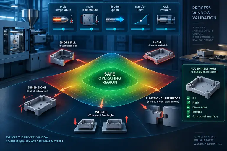
A nominal molding recipe can make acceptable samples while sitting close to short shot, flash, dimensional drift or a weak functional interface. If validation checks only one center setting, normal changes in resin, machine response and thermal state can move production outside the narrow conditions that happened to work during the trial.
Validate a process window by defining production-relevant inputs and every critical output, establishing measurement readiness, changing selected factors through a planned experiment, and confirming an operating region—not merely a best point. The approved center should have defensible margin from failure boundaries and be verified over time with production-intent material, mold, machine, auxiliaries and handling. The window is specific to that system and requires change control when key conditions change.
Define the outputs before changing process settings
List fill, appearance, dimensions, mass, mechanical or sealing functions, insert position, joining behavior and any customer-specific characteristic that can change with molding. Define acceptance method, sample conditioning, cavity identity and measurement timing. A visual-only window is inadequate when mechanical or dimensional outputs control release. Research on experimental process-window development likewise distinguishes visual acceptance from additional performance measures.
Confirm the measurement system can resolve the expected changes. Stabilize the mold and material handling, record actual melt and mold temperatures, and separate machine setpoints from observed responses. mold-temperature guide explains how to turn those readings into a transferable thermal map. Establish safe equipment and material limits from the machine, mold and resin guidance. Conditions that risk degradation, excessive pressure or mold damage are constraints, not experimental opportunities.
Choose factors by mechanism and controllability
Potential factors include melt and mold temperature, fill velocity profile, transfer method and position, pack pressure and time, cooling time, back pressure, screw recovery, clamp behavior and material moisture. Do not vary everything. Use process understanding and preliminary studies to select factors that plausibly affect the defined outputs and can be controlled in production.
Separate noise variables from control factors. Resin lot, regrind allowance, ambient conditions, operator, machine and utility variation may need blocking, monitoring or later confirmation rather than random adjustment. Record interactions that matter: higher pack pressure may improve one dimension but create flash; faster fill may change weld-line position and appearance; cooling changes can affect both cycle and post-ejection warpage.
Design trials that reveal boundaries and interactions
A one-factor-at-a-time sweep can locate obvious limits but may miss interactions. A designed experiment can vary selected factors efficiently, provided run order, replication, sample size and analysis match the question. Include center points or repeated nominal conditions to estimate repeatability and detect drift. Preserve parts by setting, cavity and time.
Do not declare every combination inside independent high-low limits acceptable. The feasible region can be curved or discontinuous because outputs conflict. Plot or tabulate each response and overlay acceptance regions. Record failure modes at the boundaries. The MDPI/PMC study on experimental molding windows shows that the window depends on part, material, machine and mold; its example values should not be copied to another project.
Select a center with operating margin
The chosen nominal setting should be inside the combined acceptable region with margin to critical boundaries, not simply the condition with the lowest cycle or prettiest surface. Consider sensitivity to measurement uncertainty and realistic production disturbance. If the window is too narrow, investigate tool venting, cooling, gate, machine capacity, material or part design rather than solving fragility with tighter operator instructions alone.
Translate the study into machine-independent intent where practical: actual temperatures, fill time, transfer behavior, part weight response and pressure limits alongside controller settings. Define permitted adjustment rules and which changes require engineering review. Operators need a controlled range and escalation path, not permission to tune any parameter until one visible defect disappears.
Confirm the window over time and maintain it
Run the nominal process long enough to include thermal stability and relevant production events. Sample across cavities and time; verify downstream assembly, inspection and packaging. If restart, material changeover or planned interruption affects the process, include those states when they matter to release. startup-scrap guide explains how to capture those states in the first-off evidence. A run-at-rate study answers capacity questions, while this work answers robustness across controlled settings.
IQ/OQ/PQ is a medical-device validation framing; in automotive work the same evidence feeds the PPAP submission. The Plastics Technology Alliance maps the two directly: its guide covers IQ/OQ/PQ mold validation together with a PPAP Level 3 submission — a first-article inspection of 3–5 shots per cavity, a 300-part production run of 1–8 hours, Gage R&R acceptance below 10% (up to 30% conditionally), and Ppk ≥ 1.67 with Cpk ≥ 1.33 — so an automotive buyer can ask for the same runs by their PPAP names instead of the IQ/OQ/PQ names. (Thresholds as stated in the Alliance guide, linked in References; the customer’s own PPAP level governs.)
Link the approved window to the setup sheet, control plan and change process. Monitor outputs that reveal movement toward a boundary. Revalidate or justify changes to resin grade, mold steel, gate, cooling, machine, controller strategy or key auxiliaries. Capability indices can summarize stable output relative to specification, but they do not prove that the experimental window was well designed or that all cavities were represented.
Evidence worksheet for the sourcing or release review
Before the press trial, agree the factor ranges, response measurements and trial combinations. Complete the worksheet with the actual cavity and time identifiers used to compare the runs.
| Evidence line | What the reviewer should be able to verify |
|---|---|
| 1. released output requirements and failure definitions | Each critical output has a specification, inspection method and failure definition; appearance alone does not cover dimensional or functional limits. |
| 2. measurement-system and conditioning readiness | The instrument/fixture can resolve expected changes and the sample age, conditioning and measurement sequence are fixed. |
| 3. actual material, mold, machine and auxiliary state | Trial records identify resin/lot, mold revision, cavity, press, auxiliaries and handling so results are tied to the tested production system. |
| 4. factor rationale and safe operating constraints | Chosen factors have a plausible effect on an output; planned combinations stay within documented material, machine and tool constraints. |
| 5. trial matrix with randomized or controlled run order | The matrix records factor combinations, repeats, run order, blocks and stabilization rules; center checks can reveal drift during the experiment. |
| 6. cavity- and time-identified response data | Raw responses retain run, cavity and time identity alongside actual temperatures, fill/transfer behavior and any adjustments. |
| 7. combined acceptable region and selected center | The retained region satisfies all required outputs at tested combinations; the nominal point has documented margin and untested areas are identified. |
| 8. production confirmation and controlled setup document | Confirmation covers relevant production events and cavities; the setup sheet separates tested conditions from narrower daily adjustment/alarm limits. |
Questions that expose weak assumptions
| Question | A useful supplier answer should include |
|---|---|
| Which output fails first when each factor moves? | Boundary-trial results pairing each changed factor or combination with its first failing output and observed mechanism. |
| Are actual process responses recorded as well as setpoints? | Controller settings plus measured melt/mold temperature, fill time, pressure/transfer response and part results, with units and measurement method. |
| What interactions could hide between independent high-low trials? | Planned combined-factor runs or justified follow-up tests; separate one-factor passes do not prove their combination passes. |
| How far is the nominal process from each unacceptable boundary? | A response map or table showing the nominal point and observed failure boundaries, with uncertain or untested regions clearly marked. |
| Does confirmation include all cavities and stable thermal conditions? | Time-ordered process records and cavity-identified parts after stabilization, including the production events required by the validation plan. |
| Which future changes trigger review or revalidation? | A controlled list covering grade, machine, tool/gate/cooling and auxiliary changes, with an owner to assess the affected outputs and confirmation scope. |
Illustrative example
A housing fills and looks acceptable at the nominal recipe, but one mounting dimension moves high when pack pressure rises and a latch becomes incomplete when transfer occurs early. A planned matrix measures both outputs, part weight and flash across cavities. The overlap is smaller than the visual-only range.
Factor-response example: one housing, five runs
The table below completes this article’s own housing example — the mounting dimension moves high as pack pressure rises, and the latch fills only when transfer is late enough. Every value is illustrative, assumed for this worked example only, and must be replaced by the mold’s real trial data. Specification: 10.00 ± 0.08 mm (USL 10.08 mm, LSL 9.92 mm).
| Run | Pack pressure (bar) | Transfer point | Mounting dimension (mm) | Latch | Result |
|---|---|---|---|---|---|
| 1 | 600 | Nominal | 9.98 | Complete | Pass |
| 2 | 800 | Nominal | 10.03 | Complete | Pass — nominal center, 0.05 mm from USL |
| 3 | 1,000 | Nominal | 10.09 | Complete | FAIL — above USL |
| 4 | 800 | Early | 10.02 | Incomplete | FAIL — latch short, dimension alone would pass |
| 5 | 800 | Late | 10.04 | Complete | FAIL — flash at the parting line |
The acceptable region is the overlap of the dimension, latch and flash limits — not the visual-only range. The margin from the nominal center (800 bar) to the flash boundary (1,000 bar) is 200 bar of pack pressure, which is the process margin the window must protect. A setting that passes dimension but fails the latch, or passes both but flashes, is outside the window even though one response looks acceptable.
The team selects a center inside that overlap and confirms it after thermal stabilization, then records escalation limits. The result is a defensible operating region rather than a single trial screenshot.
What to send for a project-specific review
For a process-window review, send the current recipe, actual process traces, selected factors and safe bounds, trial matrix, cavity-identified results and acceptance methods through the project RFQ. Include the proposed daily adjustment limits and any untested combinations.
Separate the engineering window from daily adjustment limits
The experimental window records conditions that produced acceptable outputs in a defined study. Daily setup, alarm and operator-adjustment limits may be narrower and serve different purposes. State who may adjust each control, in what sequence, and which part evidence must be checked afterward.
When the mold moves to another press, match actual process responses rather than copying percentage settings. Screw diameter, check-ring behavior, pressure availability, controller logic, nozzle, thermal equipment and robot timing can change the relationship between a displayed value and melt history.
Boundary failures are useful evidence. Short fill may define one edge, flash or overpacked dimensions another, and weld-line function a third. If those acceptable regions do not overlap with practical margin, improve mold, part, material or cell rather than calling one fragile point validated.
Retain the plan, raw results, analysis, center, ranges, setup sequence, monitoring signals and change triggers. The objective is not to freeze processing forever; it is to make future movement deliberate, bounded and traceable to part quality.
References
- Experimental Development of an Injection Molding Process Window (PMC)
- NIST assessing process stability
- NIST process capability overview
- NIST adding center points to an experiment
- Plastics Technology Alliance — IQ/OQ/PQ Mold Validation and PPAP Level 3 (medical-device framing mapped to PPAP Level 3): https://www.plasticstechnologyalliance.com/iq-oq-pq-mold-validation-and-ppap-level-3/