
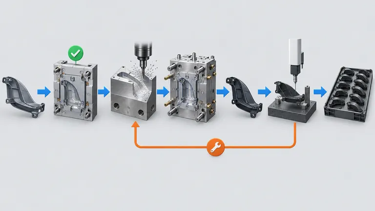
Conceptual illustration; not to scale.
An automotive mold schedule can show a confident number of weeks and still omit the approvals that control the launch. Design data changes after steel ordering, a texture drawing arrives late, T1 parts need correction, or customer validation starts only after a sample package is complete. The calendar then moves even though the toolmaker has been working continuously.
Build lead time as a dependency plan, not a single promise. Define the start event, freeze the product and material inputs, sequence design approval, steel and component procurement, machining, assembly, T1, correction, pilot evidence and customer release, and show which activities can run in parallel. Every date must carry assumptions. The illustrative schedule in this article is not an AutoMoldingPro delivery commitment and must be replaced by a project-specific plan.
The distinction from the previous T1 article is intentional: this guide explains schedule logic and delay triggers, not the full definition of production-release approval.
Define the clock before quoting the calendar
Why this matters: “Lead time from DFM approval” sounds precise until the team asks what DFM approval means. It may mean a review call, a preliminary acceptance with open issues, a released drawing, an approved mold concept or a purchase order with deposit. Different starts produce different schedules and different commercial expectations.
Choose one contractual start event and list the prerequisites. A robust start may require the released 2D drawing and 3D model, material grade, texture or surface specification, customer-specific requirements, mold standard, destination machine data, cavity count, parting-line approval, quote acceptance and payment milestone. If any item is still pending, the plan can show a forecast date but should not call the tool schedule started.
Separate product freeze from mold-design approval. The toolmaker may be able to begin layout from a stable model while a cosmetic texture or logo is pending, but steel that depends on that item should not be treated as released. Mark each activity as allowed to start, blocked, or at risk. This exposes parallel work without pretending the entire project is released.
Name the owner of every input. Engineering owns product definition; the customer or design authority owns functional approval; the moldmaker owns tool design; the material owner confirms the grade; quality defines evidence; purchasing controls commercial gates; the receiving plant confirms machine and interface information. An unowned date is not a reliable date.
Use revision control from day one. A schedule should identify the drawing/model revision, date of baseline, open technical questions and the rule for recalculating dates after a revision. If a late change affects only an interchangeable insert, the impact may be local. If it changes the gate, cooling, parting line or cavity count, the critical path can restart. The schedule should distinguish those cases rather than applying one blanket delay.
Write the clock definition on the purchase order or project schedule. It should state whether the date is a working-day forecast, whether holidays and shipping are included, and which approvals are customer-dependent. A supplier can then show a best-case and a risk-adjusted forecast without implying a guaranteed duration. When one input is missing, the plan should show the blocked activity and a provisional date rather than silently counting from an earlier conversation.
Map the build into dependency gates
Why this matters: The schedule should show what must be accepted before the next irreversible activity. This helps the buyer protect high-cost decisions and lets the supplier expose a realistic critical path.
Treat each row as a gate with a required input, an accountable owner, a defined deliverable and a dated decision; use parallel work only where a later change will not scrap or invalidate the work already started.
| Stage | Prerequisites | Main deliverable | Primary owner | Delay trigger |
|---|---|---|---|---|
| DFM and feasibility | Released or reviewable CAD, drawing, material and volume | Risk log, feasibility comments, gate/parting/cooling assumptions | Engineering and moldmaker | Missing data, unresolved interface or changed design intent |
| Mold concept and design | DFM dispositions and approved assumptions | 3D mold design, runner/cooling/ejection concept, review record | Moldmaker with customer approval | Late concept comments, changed cavity count or machine data |
| Steel and standard components | Approved steel grades, mold standard and purchase order gate | Material certificates/orders and component plan | Moldmaker/purchasing | Unapproved steel, long-lead hot runner or late standards |
| Machining and insert manufacture | Released mold design and material availability | Machined plates, cavities, cores, slides and inserts | Moldmaker | Rework, stock issue, design revision or equipment capacity |
| Assembly and bench checks | Machined components, drawings and inspection plan | Assembled mold, movement/ejection/cooling check | Moldmaker | Interference, leakage, alignment or missing components |
| T1 trial | Complete enough tool, approved resin and machine | Trial record, samples, dimensional/visual findings | Molder and quality | Short shot, flash, deformation, process instability or missing sample plan |
| Correction loop | T1 data and approved disposition | Corrected insert/tool and affected recheck | Moldmaker and design authority | New design change, welding/heat treatment or broad correction |
| Pilot or validation run | Corrected tool, process window and evidence plan | Representative parts, inspection and functional evidence | Supplier and customer quality | Gage, lab, packaging or customer-approval delay |
| Production release | Closed actions and authorized disposition | Release record, control plan and handoff package | Customer/design/quality authority | Open deviation, incomplete evidence or changed process/site |
Use the table in a network, not as nine independent date ranges. Machining may overlap with component procurement; inspection-fixture design can begin from the stable datum scheme; customer review can be scheduled during non-critical mold work. But T1 cannot be a real date if the tool is not assembled and the approved material or machine is unavailable. Mark dependencies explicitly.
Add a status field that says not started, in progress, awaiting input, under review, accepted, blocked or complete. Add a risk field that names the cause rather than using a general red or yellow label. For example, “texture revision not released” is actionable; “customer risk” is not. Show the handoff between the moldmaker and the measurement or validation team, because a finished mold without an available gage or approved material is not a ready T1.
The plan should also show the effect of a change on adjacent gates. A revised mounting hole may affect only an insert, while a new resin or cavity count can change shrinkage assumptions, runner balance, cooling and the production machine. The owner of the plan should update the critical path after the change and preserve the original baseline. This is how the buyer can distinguish a supplier delay from a customer change or an evidence dependency.
At the weekly review, calculate the date of the next decision from the current evidence, not from the original promise. A gate can be complete for the moldmaker and still blocked for the customer because the review package has not been accepted. Record that distinction. The plan should also state which activities are deliberately excluded from the date, such as destination-plant qualification or a customer laboratory test. Those exclusions are not failures; they are boundaries that stop a tooling forecast from being misread as a full vehicle-launch commitment.
Design for parallel work without hiding the critical path
Why this matters: Parallel work is valuable when the inputs are stable. It becomes dangerous when a team treats a forecast as permission to cut steel on an unresolved requirement. The schedule should show an “early work” lane and a “release-dependent work” lane.
Early work can include data audit, preliminary DFM, mold concept, machine envelope check, sourcing inquiries and fixture concept. Release-dependent work may include final cavity and core machining, texture, hot-runner manufacture, final gate details and customer-specific features. If the design authority changes the product after the release-dependent work begins, the plan should identify which items become scrap, rework or an insert change.
The critical path is the chain that controls the earliest production-release date. It may run through design approval, steel procurement, cavity machining, T1, tool correction, external testing and customer disposition. It is not always the same as the longest individual operation. A short customer approval that cannot start until a sample report is complete can control more time than a longer machining task that runs in parallel.
Include decision latency. The moldmaker can finish a review package, but the date for the next task depends on who comments, how many review cycles are included and whether the comment changes the product or only the documentation. Set a response owner and escalation path for every gate. Do not assume “approval” means no comments; define whether comments are editorial, insert-local or critical-path changes.
Also schedule external dependencies: resin availability, color approval, texture vendor, gage build, laboratory capacity, shipping, import clearance and receiving-plant machine access. For an export mold, the destination machine interface and trial plan may create a second qualification path after the tool leaves the builder. The export route is separate from a domestic production-release promise.
Use a baseline and a live look-ahead. The baseline records the approved plan; the look-ahead records what can be executed in the next period and what is blocked. When a date changes, record the cause, owner, affected gate and mitigation. A revised date without a cause is not schedule control.
Plan T1 and corrections as a learning loop
Why this matters: T1 should be scheduled as an evidence-producing event, not as a ceremonial date. A trial can produce parts and still fail to answer whether the tool is ready for a correction decision.
Before T1, freeze the trial objective, sample quantity, cavity representation, material and process assumptions, measurement state, visual standard and report due date. Confirm the machine, mold handling, resin drying, insert configuration, safety checks and measurement resources. If a feature needs a functional check, make sure the authorized mating component or gage is available before the trial.
After T1, classify findings. Separate product-definition issues, tool geometry issues, process-window issues, measurement-method issues and cosmetic or assembly issues. A short shot from an unoptimized process is not the same as a hole location created by the cavity insert. A CMM result taken with the wrong datum is not a steel correction. The classification controls both work content and schedule.
Define a correction loop with a decision deadline. The supplier should submit the finding, proposed correction, affected steel, validation method and risk to adjacent features. The design authority approves the correction scope. Local insert corrections may be scheduled while unaffected tool areas proceed; welding, heat treatment, texture or a gate-system change may require a larger replan.
Do not use a generic number of T1 loops as a guarantee. The number depends on geometry, material, tolerance, tool complexity, customer review speed and evidence. Quote the assumptions and include a correction strategy, not an unsupported promise that the mold will pass in one trial. The T1 and production-release guide remains the reference for the approval distinction; the schedule should link to its gate without copying its content.
Set a report deadline after the trial, not only a trial date. The correction meeting cannot make a reliable decision until the dimensional and visual evidence is available. Define which findings can be corrected by the toolmaker under the approved scope and which require product or customer authorization. Include the time for measurement, report review, decision, steel work, re-trial and targeted recheck. A schedule that omits these intervals is a trial schedule, not a production-release schedule.
Make the schedule buyer-usable
Why this matters: The buyer needs enough detail to see whether the supplier has understood the program, but not a false precision that no one can maintain. Request a one-page milestone plan plus a detailed dependency list for the critical path.
The milestone plan should show baseline date, forecast date, gate owner, prerequisite, evidence, status, risk and next action. The detailed list should show each long-lead item, approval cycle, machining package, trial, correction and validation activity. Define working-day convention, holidays, shipping assumptions and whether the timing begins at purchase order, data release or payment.
Illustrative example: a two-cavity interior housing has an approved CAD model but its texture specification and destination machine nozzle details are open. A supplier’s “ten-week tool lead time” is not accepted as a production date. The plan marks DFM and preliminary mold layout as early work, but final surface machining and interface release as blocked. It schedules steel and standard components only after the mold concept is accepted, and places T1 after tool assembly, machine confirmation and approved material availability.
The customer then changes the connector cutout before steel is cut. The plan records no effect on the early review but delays final cavity release. Later, T1 shows a local position issue; the supplier proposes a replaceable insert correction and a targeted recheck while the gage report is prepared. The production-release date moves only by the verified correction and customer-disposition time, not by an unexplained full restart.
This is the schedule behavior a buyer should look for: explicit gates, parallel work with stable inputs, named owners and a record of cause. Request the latest plan with automotive mold manufacturing or use the RFQ route with the target production-release decision and customer approval milestones stated.
Request a recovery plan when a date moves. The plan should identify the new critical path, work that can still run in parallel, customer decisions needed, containment or interim sample use, and the revised evidence date. Do not accept a date change without a cause and owner. A realistic schedule may contain uncertainty; it becomes useful when that uncertainty is visible and connected to a decision.
Conclusion
Define the clock, freeze inputs, map irreversible gates, show parallel work and schedule T1, correction, validation and customer disposition as linked events. Treat every duration as assumption-based until the supplier and customer agree the data, owners and evidence. Ask for a milestone plan and critical-path look-ahead, not only a single lead-time number.
References
- AIAG, Quality Core Tools — APQP and PPAP context for launch and production readiness.
- AIAG, Helpful Documents in the APQP Process — typical APQP scope including feasibility, process design, validation and feedback.
- AIAG, APQP and Control Plan FAQ — gated management, sourcing, change management and risk-mitigation topics in APQP 3rd edition.
- AutoMoldingPro, Automotive Molding Capacity Run-at-Rate — related production-capacity evidence article.